SLVS912J January 2009 – January 2016 DRV8821
PRODUCTION DATA.
- 1 Features
- 2 Applications
- 3 Description
- 4 Revision History
- 5 Pin Configuration and Functions
- 6 Specifications
- 7 Detailed Description
- 8 Application and Implementation
- 9 Power Supply Recommendations
- 10Layout
- 11Device and Documentation Support
- 12Mechanical, Packaging, and Orderable Information
Package Options
Mechanical Data (Package|Pins)
- DCA|48
Thermal pad, mechanical data (Package|Pins)
- DCA|48
Orderable Information
8 Application and Implementation
NOTE
Information in the following applications sections is not part of the TI component specification, and TI does not warrant its accuracy or completeness. TI’s customers are responsible for determining suitability of components for their purposes. Customers should validate and test their design implementation to confirm system functionality.
8.1 Application Information
The DRV8821 can be used to drive two bipolar stepper motors.
8.2 Typical Application
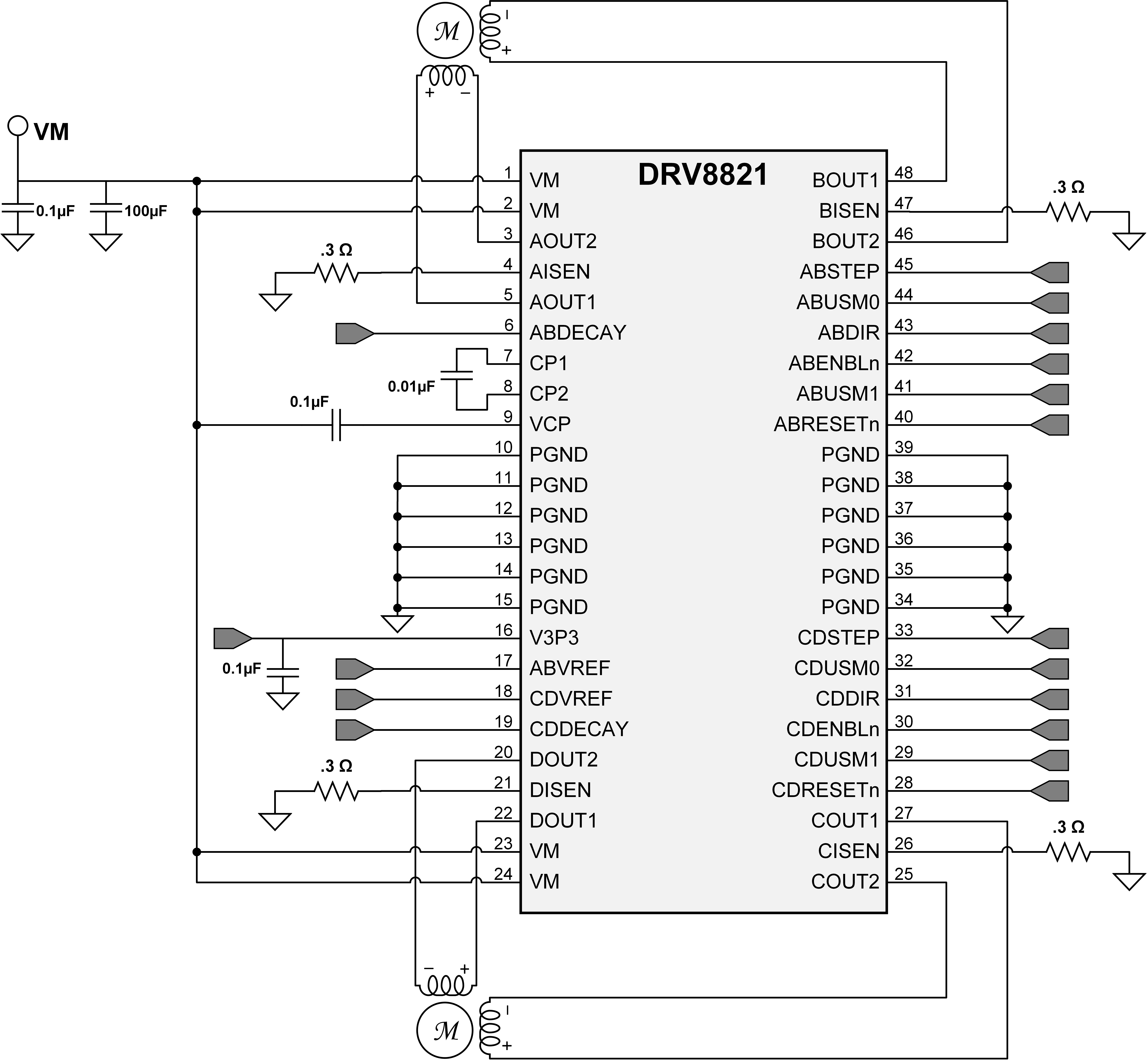 Figure 12. Typical Application Schematic
8.2.1 Design Requirements
Table 3 shows the design parameters.
Table 3. Design Parameters
| DESIGN PARAMETER | REFERENCE | EXAMPLE VALUE |
|---|---|---|
| Supply voltage | VM | 24 V |
| Motor winding resistance | RL | 7.4 Ω/phase |
| Motor step full angle | θstep | 1.8°/step |
| Target microstepping angle | nm | 1/8 step |
| Target motor speed | V | 120 rpm |
| Target full-scale current | IFS | 1 A |
8.2.2 Detailed Design Procedure
8.2.2.1 Stepper Motor Speed
The first step in configuring the DRV8821 requires the desired motor speed and stepping level. The DRV8821 can support from full step to 1/8 step mode. If the target motor speed is too high, the motor will not spin. Make sure that the motor can support the target speed. For a desired motor speed (v), a microstepping level (nm), and motor full step angle (θstep).

θstep can be found in the stepper motor data sheet or often written on the motor itself.
For DRV8821, the microstepping levels are set by the xUSM0/xUSM1 pins and can be any of the settings in Table 1. Higher microstepping means a smoother motor motion and less audible noise, but increases the switching losses and requires a higher ƒstep to achieve the same motor speed.
8.2.2.2 Current Regulation
The chopping current (ICHOP) is the maximum current driven through either winding. This quality will depend on the sense resistor value (RXISEN).

ICHOP is set by a comparator which compares the voltage across RXISEN to a reference voltage. Note that ICHOP must follow Equation 4 to avoid saturating the motor.

where
- VM is the motor supply voltage.
- RL is the motor winding resistance.
8.2.3 Application Curves
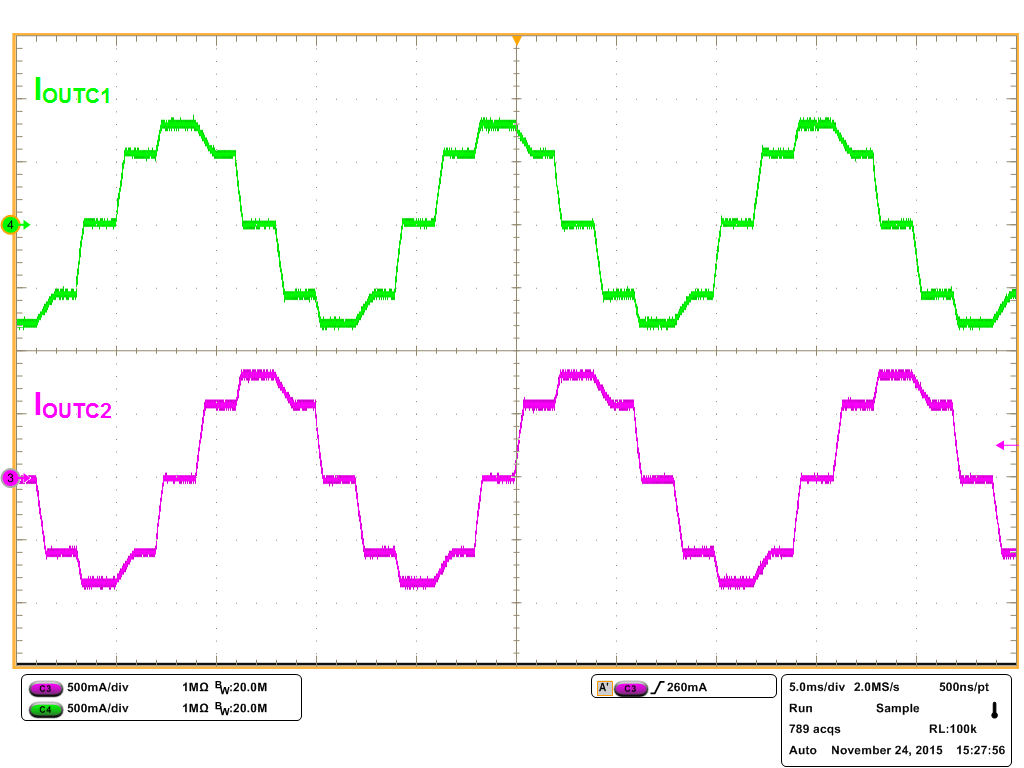 Figure 13. ½ Step Microstepping with Slow Decay
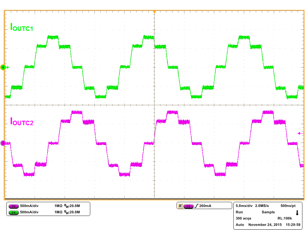 Figure 15. 1/2 Step Microstepping with Mixed Decay
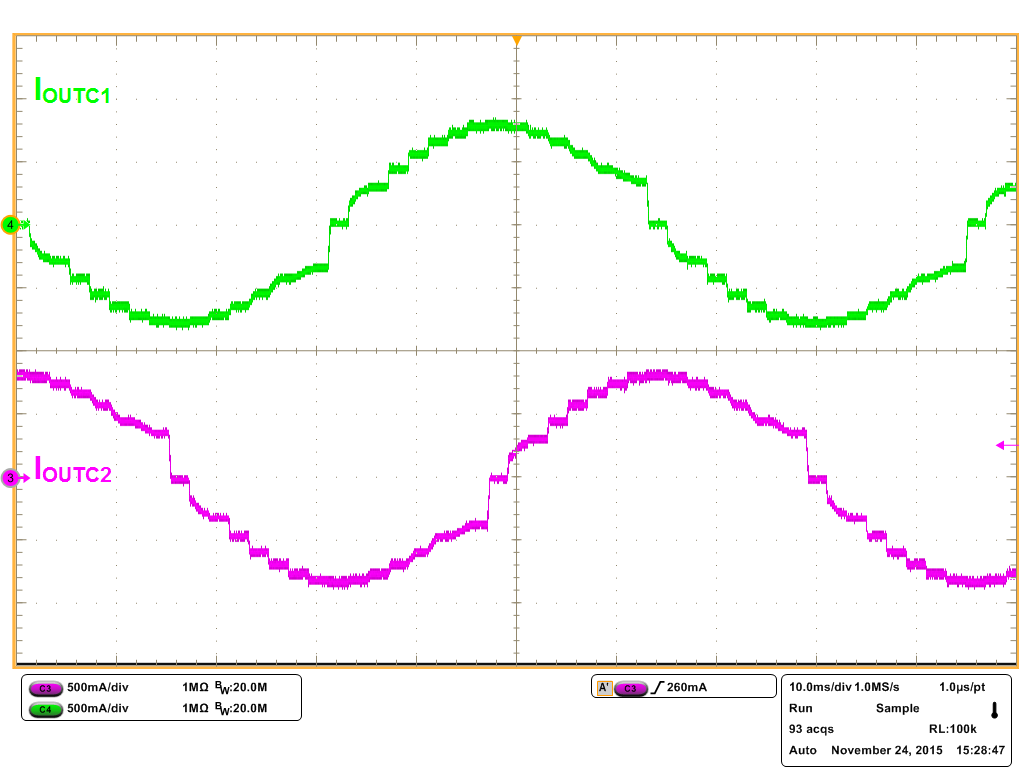 Figure 14. 1/8 Step Microstepping with Slow Decay
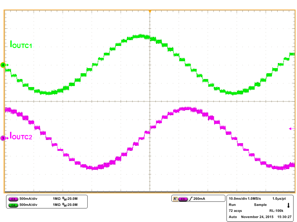 Figure 16. 1/8 Step Microstepping with Mixed Decay