SLVSB18H March 2012 – August 2016 DRV8835
PRODUCTION DATA.
- 1 Features
- 2 Applications
- 3 Description
- 4 Revision History
- 5 Pin Configuration and Functions
- 6 Specifications
- 7 Detailed Description
- 8 Application and Implementation
- 9 Power Supply Recommendations
- 10Layout
- 11Device and Documentation Support
- 12Mechanical, Packaging, and Orderable Information
Package Options
Mechanical Data (Package|Pins)
- DSS|12
Thermal pad, mechanical data (Package|Pins)
- DSS|12
Orderable Information
1 Features
- Dual-H-Bridge Motor Driver
- Capable of Driving Two DC Motors or One Stepper Motor
- Low-MOSFET ON-Resistance:
HS + LS 305 mΩ
- 1.5-A Maximum Drive Current Per H-Bridge
- Configure Bridges Parallel for 3-A Drive Current
- Separate Motor and Logic-Supply Pins:
- 0-V to 11-V Motor-Operating Supply-Voltage
- 2-V to 7-V Logic Supply-Voltage
- Separate Logic and Motor Power Supply Pins
- Flexible PWM or PHASE/ENABLE Interface
- Low-Power Sleep Mode With 95-nA Maximum Supply Current
- Tiny 2.00-mm × 3.00-mm WSON Package
2 Applications
- Battery-Powered:
- Cameras
- DSLR Lenses
- Consumer Products
- Toys
- Robotics
- Medical Devices
3 Description
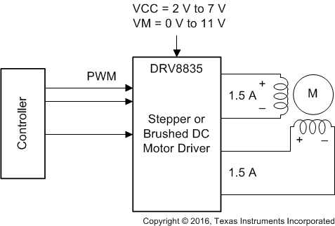
The DRV8835 provides an integrated motor driver solution for cameras, consumer products, toys, and other low-voltage or battery-powered motion control applications. The device has two H-bridge drivers, and drives two DC motors or one stepper motor, as well as other devices like solenoids. The output driver block for each consists of N-channel power MOSFETs configured as an H-bridge to drive the motor winding. An internal charge pump generates gate drive voltages.
The DRV8835 supplies up to 1.5-A of output current per H-bridge and operates on a motor power supply voltage from 0 V to 11 V, and a device power supply voltage of 2 V to 7 V.
PHASE/ENABLE and IN/IN interfaces are compatible with industry-standard devices.
Internal shutdown functions are provided for overcurrent protection, short circuit protection, undervoltage lockout, and overtemperature.
The DRV8835 is packaged in a tiny 12-pin WSON package (Eco-friendly: RoHS and no Sb/Br).
Device Information(1)
| PART NUMBER | PACKAGE | BODY SIZE (NOM) |
|---|---|---|
| DRV8835 | WSON (12) | 2.00 mm × 3.00 mm |
- For all available packages, see the orderable addendum at the end of the data sheet.
