SLVSDS7B August 2019 – November 2019 DRV8876
PRODUCTION DATA.
- 1 Features
- 2 Applications
- 3 Description
- 4 Revision History
- 5 Pin Configuration and Functions
- 6 Specifications
- 7 Detailed Description
- 8 Application and Implementation
- 9 Power Supply Recommendations
- 10Layout
- 11Device and Documentation Support
- 12Mechanical, Packaging, and Orderable Information
Package Options
Refer to the PDF data sheet for device specific package drawings
Mechanical Data (Package|Pins)
- RGT|16
- PWP|16
Thermal pad, mechanical data (Package|Pins)
Orderable Information
8.2.1.2.3.2 Transient Thermal Performance
The motor driver may experience different transient driving conditions that cause large currents to flow for a short duration of time. These may include
- Motor start-up when the rotor is not yet spinning at full speed.
- Fault conditions when there is a supply or ground short to one of the motor outputs, and the device goes into and out of overcurrent protection.
- Briefly energizing a motor or solenoid for a limited time, then de-energizing.
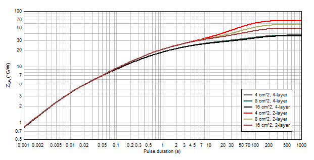
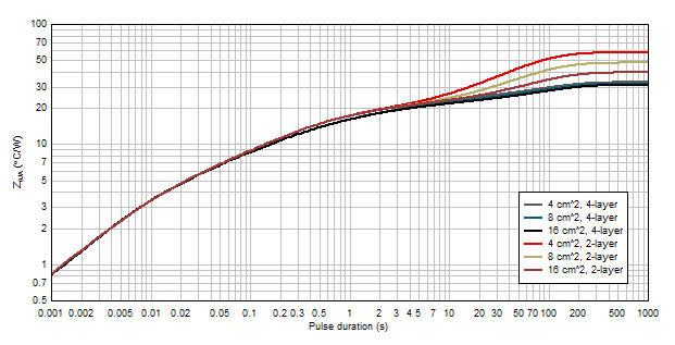
For these transient cases, the duration of drive time is another factor that impacts thermal performance. In transient cases, the thermal impedance parameter ZθJA denotes the junction-to-ambient thermal performance. Figure 27 and Figure 28 show the simulated thermal impedances for 1-oz and 2-oz copper layouts for the HTSSOP package. These graphs indicate better thermal performance with short current pulses. For short periods of drive time, the device die size and package dominates the thermal performance. For longer drive pulses, board layout has a more significant impact on thermal performance. Both graphs show the curves for thermal impedance split due to number of layers and copper area as the duration of the drive pulse duration increases. Long pulses can be considered steady-state performance.
 Figure 27. HTSSOP package junction-to-ambient thermal impedance for 1-oz copper layouts
  Figure 28. HTSSOP package Junction-to-ambient thermal impedance for 2-oz copper layouts
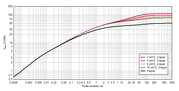
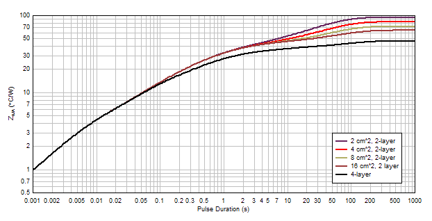
 Figure 29 and Figure 30 show the transient thermal performance for the VQFN package with 2-layer and 4-layer PCB layouts. For this simulation, only the bottom layer was varied for the 2-layer case because the pins of the VQFN package constrain the copper area under the chip on the top layer.
 Figure 29. VQFN package junction-to-ambient thermal impedance for 1-oz copper layouts
  Figure 30. VQFN package Junction-to-ambient thermal impedance for 2-oz copper layouts