SBOS160A November 1993 – January 2015 ISO122
PRODUCTION DATA.
- 1 Features
- 2 Applications
- 3 Description
- 4 Simplified Schematic
- 5 Revision History
- 6 Pin Configuration and Functions
- 7 Specifications
- 8 Detailed Description
-
9 Application and Implementation
- 9.1 Application Information
- 9.2 Typical Application
- 10Power Supply Recommendations
- 11Layout
- 12Device and Documentation Support
- 13Mechanical, Packaging, and Orderable Information
Package Options
Mechanical Data (Package|Pins)
Thermal pad, mechanical data (Package|Pins)
Orderable Information
1 Features
2 Applications
- Industrial Process Control:
- Transducer Isolator, Isolator for Thermocouples, RTDs, Pressure Bridges, and Flow Meters, 4-mA to 20-mA Loop Isolation
- Ground Loop Elimination
- Motor and SCR Control
- Power Monitoring
- PC-Based Data Acquisition
- Test Equipment
3 Description
The ISO122 is a precision isolation amplifier incorporating a novel duty cycle modulation-demodulation technique. The signal is transmitted digitally across a 2-pF differential capacitive barrier. With digital modulation the barrier characteristics do not affect signal integrity, thus resulting in excellent reliability and good high-frequency transient immunity across the barrier. Both barrier capacitors are imbedded in the plastic body of the package.
The ISO122 is easy to use. No external components are required for operation. The key specifications are 0.020% maximum nonlinearity, 50-kHz signal bandwidth, and 200-V/°C VOS drift. A power supply range of 4.5 V to 18 V and quiescent currents of 5 mA on VS1 and ±5.5 mA on VS2 make the ISO122 ideal for a wide range of applications.
The ISO122 is available in 16-pin plastic DIP and
28-lead plastic surface-mount packages.
Device Information(1)
| PART NUMBER | PACKAGE | BODY SIZE (NOM) |
|---|---|---|
| ISO122 | PDIP (16) | 17.90 mm × 7.50 mm |
| SOIC (28) | 20.01 mm × 6.61 mm |
- For all available packages, see the orderable addendum at the end of the data sheet.
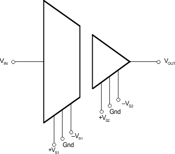
4 Simplified Schematic
