SNIS146B March 2007 – October 2017 LM95214
PRODUCTION DATA.
- 1 Features
- 2 Applications
- 3 Description
- 4 Revision History
- 5 Pin Configuration and Functions
-
6 Specifications
- 6.1 Absolute Maximum Ratings
- 6.2 ESD Ratings
- 6.3 Recommended Operating Conditions
- 6.4 Thermal Information
- 6.5 Electrical Characteristics: Temperature-to-Digital Converter
- 6.6 Logic Electrical Characteristics: Digital DC Characteristics
- 6.7 Switching Characteristics: SMBus Digital
- 6.8 Typical Characteristics
-
7 Detailed Description
- 7.1 Overview
- 7.2 Functional Block Diagram
- 7.3 Feature Description
- 7.4 Device Functional Modes
- 7.5 Register Maps
- 8 Application and Implementation
- 9 Power Supply Recommendations
- 10Layout
- 11Device and Documentation Support
- 12Mechanical, Packaging, and Orderable Information
Package Options
Mechanical Data (Package|Pins)
- NHL|14
Thermal pad, mechanical data (Package|Pins)
Orderable Information
1 Features
- Accurately Senses Die Temperature of 4 Remote ICs or Diode Junctions and Local Temperature
- Local Temperature Accuracy ±2.0°C (Maximum)
- Remote Diode Temperature Accuracy ±1.1°C (Maximum)
- Supply Voltage: 3 V to 3.6 V
- Average Supply Current (1-Hz Conversion Rate) 0.57 mA (Typical)
- Programmable Digital Filters and Analog Front-End Filter
- 0.125°C LSB Temperature Resolution
- 0.03125°C LSB Remote Temperature Resolution With Digital Filter Enabled
- Signed Format: +127.875°C/–128°C Remote Range
- Unsigned Format: 0°C/255°C Remote Range
- Remote Diode Fault Detection, Model Selection, and Offset Correction
- Mask and Status Register Support
- 3 Programmable TCRIT Outputs With Programmable Shared Hysteresis and Fault-Queue
- Programmable Conversion Rate and Shutdown Mode One-Shot Conversion Control
- SMBus 2.0 Compatible Interface, Supports TIMEOUT
- Three-Level Address Pin
2 Applications
- MCU, GPU, ASIC, FPGA, DSP, and CPU Temperature Monitoring
- Telecommunication Equipment
- Servers and Personal Computers
- Cloud Ethernet Switches
- Secure Data Centers
- Highly Integrated Medical Systems
- Precision Instruments and Test Equipment
- LED Lighting Thermal Control
- Office Electronics
- Electronic Test Equipment
- Processor and Computer System Thermal Management
3 Description
The LM95214 device is an 11-bit digital temperature sensor with a 2-wire System Management Bus (SMBus) interface that can very accurately monitor the temperature of four remote diodes as well as its own temperature. The four remote diodes can be external devices such as microprocessors, graphics processors that target the ideality of a 2N3904 transistor or diode-connected 2N3904s.
The LM95214 reports temperature in two different formats for +127.875°C/–128°C range and 0°C/255°C range. The LM95214 TCRIT1, TCRIT2 and TCRIT3 outputs are triggered when any unmasked channel exceeds its corresponding programmable limit and can be used to shutdown the system, to turn on the system fans or as a microcontroller interrupt function. The current status of the TCRIT1, TCRIT2, and TCRIT3 pins can be read back from the status registers. Mask registers are available for further control of the TCRIT outputs.
Two LM95214 remote temperature channels have programmable digital filters while the other two remote channels use a fault-queue to minimize unwanted TCRIT events when temperature spikes are encountered.
For optimum flexibility and accuracy, each LM95214 channel includes registers for offset correction. A three-level address pin allows connection of up to 3 LM95214s to the same SMBus master. The LM95214 includes power saving functions such as: programmable conversion rate, shutdown mode, and disabling of unused channels.
Device Information(1)
| PART NUMBER | PACKAGE | BODY SIZE (NOM) |
|---|---|---|
| LM95214 | WSON (14) | 4.00 mm × 4.00 mm |
- For all available packages, see the orderable addendum at the end of the data sheet.
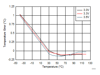
Remote 1 Temperature Error, TA=TD

4 Revision History
Changes from A Revision (March 2013) to B Revision
- Added Device Information table, Added ESD Ratings table, Feature Description section, Device Functional Modes section, Application and Implementation section, Specification section, Detailed Description section, Layout section, Device and Documentation Support section, and Mechanical, Packaging, and Orderable Information section.Go
Changes from * Revision (March 2013) to A Revision
- Changed layout of National Data Sheet to TI formatGo