SNVS458D June   2007  – October 2016 LP55281

PRODUCTION DATA.  

  1. Features
  2. Applications
  3. Description
  4. Revision History
  5. Pin Configuration and Functions
  6. Specifications
    1. 6.1 Absolute Maximum Ratings
    2. 6.2 ESD Ratings
    3. 6.3 Recommended Operating Conditions
    4. 6.4 Thermal Information
    5. 6.5 Electrical Characteristics
    6. 6.6 SPI Timing Requirements
    7. 6.7 I2C Timing Requirements
    8. 6.8 Boost Converter Typical Characteristics
    9. 6.9 RGB Driver Typical Characteristics
  7. Detailed Description
    1. 7.1 Overview
    2. 7.2 Functional Block Diagram
    3. 7.3 Feature Description
      1. 7.3.1 Magnetic Boost DC-DC Converter
        1. 7.3.1.1 Boost Standby Mode
        2. 7.3.1.2 Boost Output Voltage Control
        3. 7.3.1.3 Boost Frequency Control
      2. 7.3.2 Functionality of RGB LED Outputs (R1-4, G1-4, B1-4)
        1. 7.3.2.1 PWM Control Timing
      3. 7.3.3 Audio Synchronization
        1. 7.3.3.1 Control of Audio Synchronization
        2. 7.3.3.2 ALED Driver
          1. 7.3.3.2.1 Adjustment of ALED Driver
      4. 7.3.4 LED Test Interface
        1. 7.3.4.1 LED Test Procedure
        2. 7.3.4.2 LED Test Time Estimation
      5. 7.3.5 7-V Shielding
    4. 7.4 Device Functional Modes
      1. 7.4.1 Modes Of Operation
    5. 7.5 Programming
      1. 7.5.1 SPI Interface
      2. 7.5.2 I2C Compatible Serial Bus Interface
        1. 7.5.2.1 Interface Bus Overview
        2. 7.5.2.2 Data Transactions
        3. 7.5.2.3 Acknowledge Cycle
        4. 7.5.2.4 Acknowledge After Every Byte Rule
        5. 7.5.2.5 Addressing Transfer Formats
        6. 7.5.2.6 Control Register Write Cycle
        7. 7.5.2.7 Control Register Read Cycle
    6. 7.6 Register Maps
  8. Application and Implementation
    1. 8.1 Application Information
    2. 8.2 Typical Application
      1. 8.2.1 Design Requirements
      2. 8.2.2 Detailed Design Procedure
        1. 8.2.2.1 Recommended External Components
          1. 8.2.2.1.1 Output Capacitor, COUT
          2. 8.2.2.1.2 List Of Recommended External Components
          3. 8.2.2.1.3 Input Capacitor, CIN
          4. 8.2.2.1.4 Output Diode, D1
          5. 8.2.2.1.5 Inductor, L
      3. 8.2.3 Application Curves
    3. 8.3 Initialization Set Up Example
  9. Power Supply Recommendations
  10. 10Layout
    1. 10.1 Layout Guidelines
      1. 10.1.1 Boost Output Capacitor Placement
      2. 10.1.2 Schottky Diode Placement
      3. 10.1.3 Inductor Placement
      4. 10.1.4 Boost Input Capacitor Placement
    2. 10.2 Layout Example
  11. 11Device and Documentation Support
    1. 11.1 Device Support
      1. 11.1.1 Third-Party Products Disclaimer
    2. 11.2 Related Documentation
    3. 11.3 Receiving Notification of Documentation Updates
    4. 11.4 Community Resources
    5. 11.5 Trademarks
    6. 11.6 Electrostatic Discharge Caution
    7. 11.7 Glossary
  12. 12Mechanical, Packaging, and Orderable Information

Package Options

Mechanical Data (Package|Pins)
Thermal pad, mechanical data (Package|Pins)
Orderable Information

Features

  • Audio Synchronization for a Single Fun-Light LED
  • Four PWM Controlled RGB LED Drivers
  • High-Efficiency Boost DC-DC Converter
  • SPI or I2C-Compatible Interface
  • Two Addresses in I2C-Compatible Interface
  • LED Connectivity Test Through the Serial Interface

Applications

  • Cellular Phones
  • PDAs, MP3 Players

Description

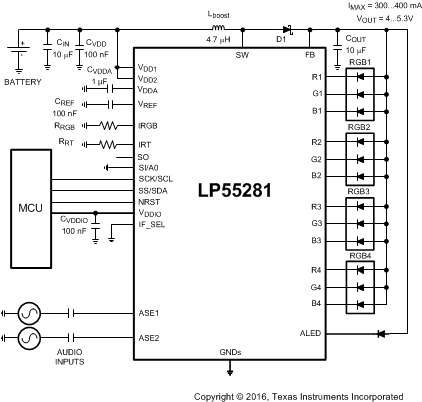
The LP55281 device is a quadruple RGB LED driver for handheld devices. It can drive 4 RGB LED sets and a single fun-light LED. The boost DC-DC converter drives high current loads with high efficiency. The RGB driver can drive individual color LEDs or RGB LEDs powered from boost output or external supply. Built-in audio synchronization feature allows user to synchronize the fun-light LED to audio inputs. The flexible SPI or I2C interface allows easy control of LP55281. A small YZR0036 or YPG0036 package, together with minimum number of external components, is a best fit for handheld devices. The LP55281 also has an LED test feature, which can be used, for example, in production for checking the LED connections.

Device Information(1)

PART NUMBER PACKAGE BODY SIZE (NOM)
LP55281 DSBGA (36) 2.982 mm × 2.982 mm
  1. For all available packages, see the orderable addendum at the end of the data sheet.

Typical Application

LP55281 20201101.gif