SLVSCC8A May 2014 – December 2014 TPS2513A-Q1 , TPS2514A-Q1
PRODUCTION DATA.
- 1 Features
- 2 Applications
- 3 Description
- 4 Revision History
- 5 Pin Configuration and Functions
- 6 Specifications
- 7 Detailed Description
- 8 Applications and Implementation
- 9 Power Supply Recommendations
- 10Layout
- 11Device and Documentation Support
Package Options
Mechanical Data (Package|Pins)
- DBV|6
Thermal pad, mechanical data (Package|Pins)
Orderable Information
8 Applications and Implementation
8.1 Application Information
The device is a dual channel USB charging port controller. It can be used for automotive USB charging port to support universal charging.
8.2 Typical Application
 Figure 12. Typical Application Schematic, Dual Ports Charger
8.2.1 Design Requirements
For dual USB ports, request that both ports support fast charge portable device compatible with divider 3, 1.2 V, and BC1.2 shorted mode.
8.2.2 Detailed Design Procedure
8.2.2.1 USB Power Switch
Some chargers requests that the USB port have an overcurrent protection when short circuits are encountered, TPS2561A-Q1 (SLVSCC6) is recommended.
The TPS2513A-Q1 divider 3 mode can support a maximum charging current up to 2.4 A.
When set, the TPS2561A-Q1 current limit (RILIM) should keep each channel current limit above 2.4 A. For the correct current limit setting, refer to the TPS2561A-Q1 data sheet.
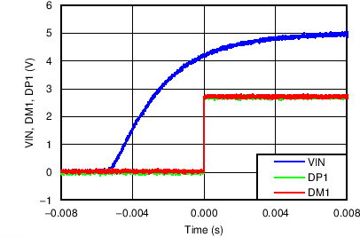
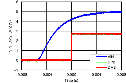
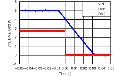
8.2.3 Application Curves