SLLSET7C May 2016 – May 2016 TRS3122E
PRODUCTION DATA.
- 1 Features
- 2 Applications
- 3 Description
- 4 Revision History
- 5 Pin Configuration and Functions
-
6 Specifications
- 6.1 Absolute Maximum Ratings
- 6.2 ESD Ratings
- 6.3 Recommended Operating Conditions
- 6.4 Thermal Characteristics
- 6.5 Power and Status Electrical Characteristics
- 6.6 Driver Electrical Characteristics
- 6.7 Receiver Electrical Characteristics
- 6.8 Driver Switching Characteristics
- 6.9 Receiver Switching Characteristics
- 6.10 Power and Status Switching Characteristics
- 6.11 Typical Characteristics
- 7 Parameter Measurement Information
- 8 Detailed Description
- 9 Application and Implementation
- 10Power Supply Recommendations
- 11Layout
- 12Device and Documentation Support
- 13Mechanical, Packaging, and Orderable Information
Package Options
Mechanical Data (Package|Pins)
- RGE|24
Thermal pad, mechanical data (Package|Pins)
- RGE|24
Orderable Information
1 Features
- Extended VCC operating nodes: 1.8 V, 3.3 V, or 5.0 V
- Unique Tripler Charge Pump Architecture Enables Low VCC of 1.8V While Maintaining Compatibility with 3.3 V and 5 V Supplies
- Integrated Level-Shifting Functionality Eliminates the Need for External Power or Additional Level Shifter While Interfacing with Low-Voltage MCUs
- Enhanced ESD Protection on RIN Inputs and DOUT Outputs
- ±15 kV IEC 61000-4-2 Air-Gap Discharge
- ±8 kV IEC 61000-4-2 Contact Discharge
- ±15 kV Human-Body Model
- Specified 1000-kbps Data Rate
- Auto Powerdown Plus Feature
- Low 0.5uA Shutdown Supply Current
- Meets or Exceeds Compatibility Requirements of RS-232 Interface
- For 2.5 V Single Supply Applications, Consider TRS3318E as an Optimized Solution
2 Applications
3 Description
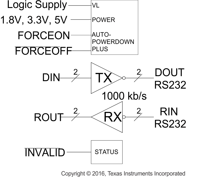
The TRS3122E is a two-driver and two-receiver RS-232 interface device, with split supply pins for mixed-voltage operation. All RS-232 inputs and outputs are protected to ±15 kV using the IEC 61000-4-2 Air-Gap Discharge method, ±8 kV using the IEC 61000-4-2 Contact Discharge method, and ±15 kV using the Human-Body Model.
The charge pump requires five small 0.1-μF capacitors for operation from as low as a 1.8-V supply. The TRS3122E is capable of running at data rates up to 1000 kbps, while maintaining RS-232-compatible output levels.
The TRS3122E has a unique VL pin that allows operation in mixed-logic voltage systems. Both driver in (DIN) and receiver out (ROUT) logic levels are pin programmable through the VL pin. This eliminates the need for additional voltage level shifter while interfacing with low-voltage microcontrollers or UARTs.
Auto Powerdown Plus automatically places the device in a low power mode when the device has not received or transmitted data for more than 30 seconds. This feature makes this device a very attractive option for battery powered or other power-sensitive applications.
Device Information(1)
| PART NUMBER | PACKAGE (PINS) | BODY SIZE (NOM) |
|---|---|---|
| TRS3122ERGER | RGE (24) | 4.00 mm × 4.00 mm |
- For all available packages, see the orderable addendum at the end of the datasheet.
Feature Diagram
