SLUSC05D July 2014 – May 2016 UCC28880
PRODUCTION DATA.
- 1 Features
- 2 Applications
- 3 Description
- 4 Revision History
- 5 Pin Configuration and Functions
- 6 Specifications
- 7 Detailed Description
-
8 Application and Implementation
- 8.1 Application Information
- 8.2
Typical Application
- 8.2.1
12-V, 100-mA Low-Side Buck Converter
- 8.2.1.1 Design Requirements
- 8.2.1.2
Detailed Design Procedure
- 8.2.1.2.1 Custom Design with WEBENCH Tools
- 8.2.1.2.2 Input Stage (RF, D2, D3, C1, C2, L2)
- 8.2.1.2.3 Regulator Capacitor (CVDD)
- 8.2.1.2.4 Freewheeling Diode (D1)Freewheeling Diode (D1) section.
- 8.2.1.2.5 Output Capacitor (CL)
- 8.2.1.2.6 Load Resistor (RL)
- 8.2.1.2.7 Inductor (L1)
- 8.2.1.2.8 Feedback Path (Q1, RFB1, RFB2)
- 8.2.1.3 Application Curves
- 8.2.2 12-V, 100-mA, High-Side Buck Converter
- 8.2.3 Additional UCC28880 Application Topologies
- 8.2.1
12-V, 100-mA Low-Side Buck Converter
- 9 Power Supply Recommendations
- 10Layout
- 11Device and Documentation Support
- 12Mechanical, Packaging, and Orderable Information
Package Options
Mechanical Data (Package|Pins)
- D|7
Thermal pad, mechanical data (Package|Pins)
Orderable Information
1 Features
- Integrated Power MOSFET (Switch) Rated to
700-V Drain-to-Source Voltage - Integrated High-Voltage Current Source for Internal Low-Voltage Supply Generation
- Soft Start
- Self-Biased Switcher (Start Up and Operation Directly from Rectified Mains Voltage)
- Supports Buck, Buck-Boost and Flyback Topologies
- <100-μA Device Quiescent Current
- Robust Performance with Inductor Current Runaway Prevention
- Thermal Shutdown
- Protection
- Current Limit
- Overload and Output Short Circuit
- Create a Custom Design Using the UCC28880 with the WEBENCH Power Designer
2 Applications
3 Description
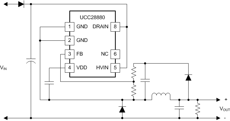
The UCC28880 integrates the controller and a 700-V power MOSFET into one monolithic device. The device also integrates a high-voltage current source, enabling start up and operation directly from the rectified mains voltage.
The low quiescent current of the device enables excellent efficiency. With the UCC28880 the most common converter topologies, such as buck, buck-boost and flyback can be built using a minimum number of external components.
The UCC28880 incorporates a soft-start feature for controlled start up of the power stage which minimizes the stress on the power-stage components.
Device Information(1)
| PART NUMBER | PACKAGE | BODY SIZE (NOM) |
|---|---|---|
| UCC28880 | SOIC (7) | 5.00 mm × 6.20 mm |
- For all available packages, see the orderable addendum at the end of the data sheet.

