SLLA575 June 2022 DRV10987 , MCF8316A , MCT8316A
2.1.1 Align
The MCF8316A aligns the motor by injecting a DC current through a particular phase pattern for a certain duration of time. Below are the dominant parameters that impact startup time during align and open loop operation.
- Align time [ALIGN_TIME]
- Align or slow first cycle current limit [ALIGN_OR_SLOW_CURRENT_LIMIT]
- Starting frequency of first cycle [FIRST_CYCLE_FREQ_SEL]
- Open loop acceleration coefficient A1 [OL_ACC_A1]
- Open loop acceleration coefficient A2 [OL_ACC_A2]
- Auto handoff from open to closed loop [AUTO_HANDOFF_EN]
- Minimum BEMF for auto handoff [AUTO_HANDOFF_MIN_BEMF]
Figure 2-1 shows the Q-axis current iqref and motor electrical frequency fele with respect to time. During align, the motor driver ramps up the phase current from zero to the configured ALIGN_OR_SLOW_CURRENT_LIMIT. Current ramps at the rate configured by ALIGN_SLOW_RAMP_RATE for the duration configured by ALIGN_TIME.
After the align time, the MCF8316A begins to accelerate the motor in open loop with the first cycle open loop frequency configured by FIRST_CYCLE_FREQ_SEL and ramps up the motor speed to the handoff frequency fele.
To minimize the motor startup time during align operation, it is recommended to decrease the align time [ALIGN_TIME] and increase the align or slow first cycle current limit [ALIGN_OR_SLOW_CURRENT_LIMIT] to a value closer to the rated current of the motor.
To minimize the motor startup time in open loop operation, it is recommended to increase the Starting frequency of first cycle [FIRST_CYCLE_FREQ_SEL], open loop acceleration coefficient A1 [OL_ACC_A1] and A2 [OL_ACC_A2], enable auto handoff [AUTO_HANDOFF_EN] and set the minimum BEMF for auto handoff [AUTO_HANDOFF_MIN_BEMF] to 0 mV.
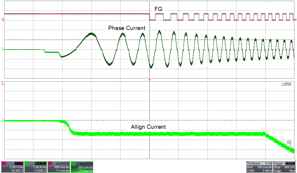
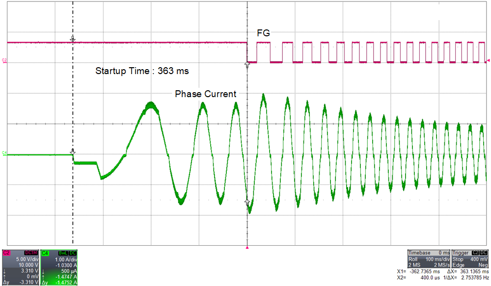
Figure 2-2 shows the FG and phase current of a BLDC motor. FG is configured to output pulses in closed loop. This is to know exactly at what point the motor enters closed loop. Bottom half of the figure shows the phase current that is zoomed to show the align current. The align current should be a DC current without any oscillations. Figure 2-3 shows the time taken for the BLDC motor to enter closed loop which is 363 ms.
 Figure 2-2 Phase Current and FG During
Align
 Figure 2-3 Time Taken to Enter Closed
Loop in Align