Dear all
I am a student working on ECG amplifier design. Basically, I followed the design and suggestions from the a paper (see below link) with modifications using INA326 and OPA333/2333. In addition, I have read through the subject of <<INA326 EMG amplifier>> in this forum.
I have built a testing board and done measurements. I am facing two problems at this stage:
1. I used OPA333 to implement an activate electrode amplifier, which is actually a emitter follower without biasing, see the paper. I found its input impedance is not high enough, which is about 10Mohm. I expect it should higher than 1G ohm. My questions are
http://e2e.ti.com/cfs-file.ashx/__key/CommunityServer.Discussions.Components.Files/14/8551.Fabric_2D00_Based-Active-Electrode-Design-and.pdf
1.1 What is the input impedance of OPA333 with emitter follower configuration? I could not find it from the datasheet.
1.2 Any suggestions to make its input impedance higher or I have to change another amplifier?
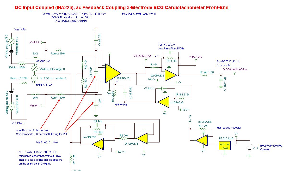
2. This question is about Driven Right Leg (DRL). I found that the DC level of DRL signal, see below, from INA326 is not exactly 1/2V+. This makes the DRL circuit to be saturated. Do you guys have any solution for improvement or avoid this.

Thank you very much!
Xijun