SLOS912D February 2015 – July 2015 ALM2402-Q1
PRODUCTION DATA.
- 1 Features
- 2 Applications
- 3 Description
- 4 Simplified Schematic
- 5 Revision History
- 6 Pin Configuration and Functions
- 7 Specifications
- 8 Detailed Description
- 9 Applications and Implementation
- 10Power Supply Recommendations
- 11Layout
- 12Device and Documentation Support
- 13Mechanical, Packaging, and Orderable Information
Package Options
Mechanical Data (Package|Pins)
Thermal pad, mechanical data (Package|Pins)
Orderable Information
1 Features
- High Output Current Drive: 400 mA Continuous (Per Channel)
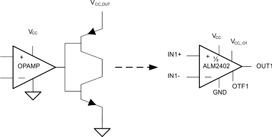
- Op-amp With Discrete Power Boost Buffer Replacement
- Wide Supply Range for Both Supplies (up to 16 V)
- Over Temperature Shutdown
- Current Limit
- Shutdown Pin for Low Iq Applications
- Stable with Large Capacitive Loads (up to 3 µF)
- Zero Crossover Distortion
- Qualified for Automotive Applications
- AEC-Q100 Qualified With the Following Results:
- Low Offset Voltage: 1 mV (typ)
- Internal RF/EMI Filter
- Available in 3.00 mm x 3.00 mm 12 Pin WSON (DRR) With Thermal Pad
2 Applications
- Large Capacitive Loads
- Cable Shields
- Reference Buffers
- Power-FET/IGBT Gates
- Super Caps
- Tracking LDO
- Inductive Loads
- Resolvers
- Bipolar DC & Servo Motors
- Solenoids & Valves
3 Description
The ALM2402-Q1 is a dual high voltage, high current op-amp with protection features that are optimal for driving low impedances and/or high ESR capacitive loads. ALM2402-Q1 operates with single or split power supplies from 5.0 V to 16 V and can output up to 400 mA DC.
Each op-amp includes over-temperature flag/shut-down. It also includes separate supply pins for each output stage that allow the user to apply a lower voltage on the output to limit the Voh and henceforth the on-chip power dissipation.
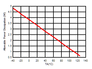
The ALM2402 is packaged in a 12 pin leadless DRR package and 14 pin leaded HTSSOP (preview). Both include a thermally conductive power pad that facilitates heat sinking. The very low thermal impedance of these packages enable optimal current drive with minimal die temperature increase. Providing customers with the ability to drive high currents in harsh temperature conditions. Maximum power dissipation can be determined in the figure below.
Device Information(1)
| PART NUMBER | PACKAGE | BODY SIZE (NOM) |
|---|---|---|
| ALM2402-Q1 | SON (12) | 3.00 mm x 3.00 mm |
| HTSSOP (14) | 5.00 mm x 4.40 mm |
- For all available packages, see the orderable addendum at the end of the data sheet.
4 Simplified Schematic

Maximum Power Dissipation vs Temperature
