SLUSBE4B January 2014 – June 2014
PRODUCTION DATA.
- 1 Features
- 2 Applications
- 3 Description
- 4 Simplified Diagram
- 5 Revision History
- 6 Pin Configuration and Functions
- 7 Specifications
-
8 Detailed Description
- 8.1 Overview
- 8.2 Functional Block Diagram
- 8.3
Feature Description
- 8.3.1 A6 Coil Specification
- 8.3.2 EMI Shield
- 8.3.3 I2C Interface
- 8.3.4 Active or Passive Wake-up State
- 8.3.5 Smart Key or Immobilizer Handling
- 8.3.6 Option Select Pins
- 8.3.7 LED Modes
- 8.3.8 Foreign Object Detection (FOD) and Parasitic Metal Object Detect (PMOD) CalibrationForeign Object Detection (FOD) and Parasitic Metal Object Detect (PMOD) Calibration description.
- 8.3.9 Shut Down via External Thermal Sensor or Trigger
- 8.3.10 Fault Handling and Indication
- 8.3.11 Power Transfer Start Signal
- 8.3.12 Power-On Reset
- 8.3.13 External Reset, RESET Pin
- 8.3.14 Trickle Charge and CS100
- 8.3.15 Over-Voltage Protection Over-Voltage Protection section.
- 8.4 Device Functional Modes
- 9 Applications and Implementation
- 10Power Supply Recommendations
- 11Layout
- 12Device and Documentation Support
- 13Mechanical, Packaging, and Orderable Information
Package Options
Mechanical Data (Package|Pins)
- RGZ|48
Thermal pad, mechanical data (Package|Pins)
- RGZ|48
Orderable Information
1 Features
- Expanded Free Positioning Using Three Coil Transmit Array
- AEC-Q100 Qualified for Automotive Applications
- Conforms to Wireless Power Consortium (WPC) A6 Transmitter Type Specification
- I2C Interface to Enable Control and Communication With Host Controllers, that is Read Tx and Rx Stats, Start Tx, and Shift Tx Operating Frequency
- WPC v1.1 Compliant, Including Improved Foreign Object Detection (FOD) Method
- Enhanced Parasitic Metal Object Detection (PMOD) for WPC v1.0 Receivers Protection
- Digital Demodulation Reduces Components
- Over-Current Protection
- LED Indication of Charging State and Fault Status
2 Applications
- WPC 1.1 Wireless Chargers:
- In Cars and Other Vehicle Accessories
- Qi-Certified Smart Phones and Other Handhelds
- Industrial and Medical Applications
- See www.ti.com/wirelesspower for More Information on TI's Wireless Charging Solutions
3 Description
The bq500414Q is an AEC-Q100 qualified free-positioning digital wireless power controller designed for automotive applications. It integrates all functions required to control wireless power transfer to a WPC compliant receiver. It is WPC v1.1 ready and designed for 12-V systems; however, the bq500414Q is applicable to other supply voltages. The bq500414Q pings the surrounding environment for WPC compliant devices to be powered. Once a WPC compliant device is detected, the bq500414Q reads the packet feedback from the powered device and manages the power transfer. A charging area of 70-mm x 20-mm provides flexible receiver placement on a transmitter pad. The bq500414Q supports both Parasitic Metal Object Detection (PMOD) and Foreign Object Detection (FOD) by continuously monitoring the transmitted and received power of the system, protecting the device from over heating. Should any abnormal condition develop during power transfer, the bq500414Q handles it and provides fault indicator outputs. Comprehensive protection features provide a robust design to protect the system in all receiver placements.
The bq500414Q is available in an area saving 48-pin, 7-mm × 7-mm VQFN package and operates over a temperature range from –40°C to 85°C.
Device Information(1)
| DEVICE NAME | PACKAGE | BODY SIZE |
|---|---|---|
| bq500414Q | VQFN (48) | 7 mm × 7 mm |
- For all available packages, see the orderable addendum at the end of the data sheet.
4 Simplified Diagram
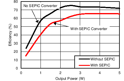
Efficiency Versus System Output Power With A6 Tx Coil