SWAS032F July 2013 – February 2015 CC3200
PRODUCTION DATA.
- 1Device Overview
- 2Revision History
- 3Terminal Configuration and Functions
-
4Specifications
- 4.1 Absolute Maximum Ratings
- 4.2 Handling Ratings
- 4.3 Power-On Hours
- 4.4 Recommended Operating Conditions
- 4.5 Brown-Out and Black-Out
- 4.6 Electrical Characteristics (3.3 V, 25°C)
- 4.7 WLAN Receiver Characteristics
- 4.8 WLAN Transmitter Characteristics
- 4.9 Current Consumption
- 4.10 Thermal Characteristics for RGC Package
- 4.11 Timing and Switching Characteristics
- 5Detailed Description
- 6Applications and Implementation
- 7Device and Documentation Support
- 8Mechanical Packaging and Orderable Information
Package Options
Mechanical Data (Package|Pins)
- RGC|64
Thermal pad, mechanical data (Package|Pins)
- RGC|64
Orderable Information
7 Device and Documentation Support
7.1 Device Support
7.1.1 Development Support
The CC3200 evaluation board includes a set of tools and documentation to help the user during the development phase.
7.1.1.1 PinMux Tool
The CC3200 device uses pin multiplexing extensively to accommodate the large number of peripheral functions in the smallest possible package. The PinMux tool is a utility used to select the appropriate pin multiplexing configuration that meets the end application requirements. The PinMux tool makes it easy to understand the various pin multiplexing options and enables the best configuration to be chosen without error.
7.1.1.2 Radio Tool
The SimpleLink radio tool is a utility for operating and testing the CC3200 chipset designs during development of the application board. The CC3200 device has an auto-calibrated radio that enables easy connection to the antenna without requiring expertise in radio circuit design.
7.1.1.3 Uniflash Flash Programmer
The Uniflash flash programmer utility allows end users to communicate with the SimpleLink device to update the serial flash. The easy GUI interface enables flashing of files (including read-back verification option), storage format (secured and nonsecured formatting), version reading for boot loader and chip ID, and so on.
7.1.2 Device Nomenclature
To designate the stages in the product development cycle, TI assigns prefixes to the part numbers of the CC3200 device and support tools (see Figure 7-1).
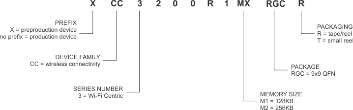 Figure 7-1 CC3200 Device Nomenclature
7.2 Documentation Support
The following documents provide support for the CC3200 device.
| SWRU372 | CC3200 SimpleLink Wi-Fi and IoT Solution With MCU LaunchPad Getting Started Guide |
| SWRU367 | CC3200 SimpleLink Wi-Fi and IoT Solution With MCU Technical Reference Manual |
| SWRU369 | CC3200 SimpleLink Wi-Fi and IoT Solution With MCU Programmer's Guide |
| SWRU370 | CC3100 and CC3200 SimpleLink Wi-Fi and IoT Solution Layout Guidelines |
| SWRC289 | CC3200 SimpleLink Wi-Fi and IoT Solution With MCU LaunchPad Board Design Files |
7.3 Community Resources
The following links connect to TI community resources. Linked contents are provided "AS IS" by the respective contributors. They do not constitute TI specifications and do not necessarily reflect TI's views; see TI's Terms of Use.
-
TI E2E™ Online Community TI's Engineer-to-Engineer (E2E) Community. Created to foster collaboration among engineers. At e2e.ti.com, you can ask questions, share knowledge, explore ideas and help solve problems with fellow engineers.
-
TI Embedded Processors Wiki Texas Instruments Embedded Processors Wiki. Established to help developers get started with Embedded Processors from Texas Instruments and to foster innovation and growth of general knowledge about the hardware and software surrounding these devices.
7.4 Trademarks
Internet-On-a-Chip, SmartConfig, E2E are trademarks of Texas Instruments.
Cortex is a registered trademark of ARM Limited.
ARM is a registered trademark of ARM Physical IP, Inc.
Macrocell is a trademark of Kappa Global Inc.
Wi-Fi CERTIFIED is a trademark of Wi-Fi Alliance.
Wi-Fi Direct is a registered trademark of Wi-Fi Alliance.
ZigBee is a registered trademark of ZigBee Alliance.
All other trademarks are the property of their respective owners.
7.5 Electrostatic Discharge Caution

This integrated circuit can be damaged by ESD. Texas Instruments recommends that all integrated circuits be handled with appropriate precautions. Failure to observe proper handling and installation procedures can cause damage.
ESD damage can range from subtle performance degradation to complete device failure. Precision integrated circuits may be more susceptible to damage because very small parametric changes could cause the device not to meet its published specifications.
7.6 Glossary
SLYZ022 — TI Glossary.
This glossary lists and explains terms, acronyms, and definitions.