SNVS038H July 1999 – January 2015 LM1085
PRODUCTION DATA.
- 1 Features
- 2 Applications
- 3 Description
- 4 Revision History
- 5 Pin Configuration and Functions
- 6 Specifications
- 7 Detailed Description
-
8 Application and Implementation
- 8.1 Application Information
- 8.2
Typical Applications
- 8.2.1 1.2-V to 15-V Adjustable Regulator
- 8.2.2 Adjustable at 5 V
- 8.2.3 5-V Regulator with Shutdown
- 8.2.4 Battery Charger
- 8.2.5 Adjustable Fixed Regulator
- 8.2.6 Regulator with Reference
- 8.2.7 High Current Lamp Driver Protection
- 8.2.8 Battery Backup Regulated Supply
- 8.2.9 Ripple Rejection Enhancement
- 8.2.10 Automatic Light Control
- 8.2.11 Generating Negative Supply Voltage
- 8.2.12 Remote Sensing
- 9 Power Supply Recommendations
- 10Layout
- 11Device and Documentation Support
- 12Mechanical, Packaging, and Orderable Information
Package Options
Mechanical Data (Package|Pins)
Thermal pad, mechanical data (Package|Pins)
- KTT|3
Orderable Information
8 Application and Implementation
NOTE
Information in the following applications sections is not part of the TI component specification, and TI does not warrant its accuracy or completeness. TI’s customers are responsible for determining suitability of components for their purposes. Customers should validate and test their design implementation to confirm system functionality.
8.1 Application Information
The LM1085 is versatile in its applications, including uses in programmable output regulation and local on-card regulation. Or, by connecting a fixed resistor between the ADJUST and OUTPUT terminals, the LM1085 can function as a precision current regulator. An optional output capacitor can be added to improve transient response. The ADJUST terminal can be bypassed to achieve very high ripple-rejection ratios, which are difficult to achieve with standard three-terminal regulators. Please note, in the following applications, if ADJ is mentioned, it makes use of the adjustable version of the part, however, if GND is mentioned, it is the fixed voltage version of the part.
8.2 Typical Applications
8.2.1 1.2-V to 15-V Adjustable Regulator
This part can be used as a simple low drop out regulator to enable a variety of output voltages needed for demanding applications. By using an adjustable R2 resistor a variety of output voltages can be made possible as shown in Figure 15 based on the LM1085-ADJ.
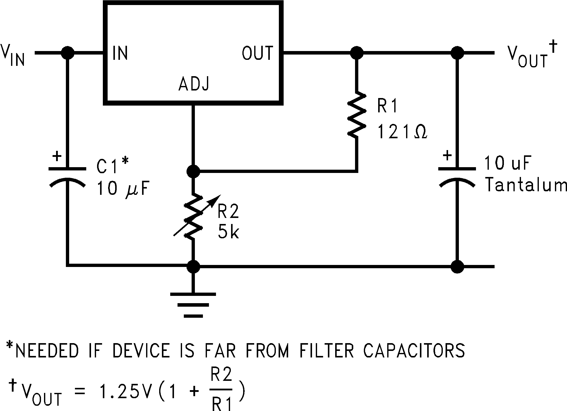 Figure 15. 1.2-V to 15-V Adjustable Regulator
8.2.1.1 Design Requirements
The device component count is very minimal, employing two resistors as part of a voltage divider circuit and an output capacitor for load regulation.
8.2.1.2 Detailed Design Procedure
The voltage divider for this part is set based on the equation in Figure 15, where R1 is the upper feedback resistor R2 is the lower feedback resistor.
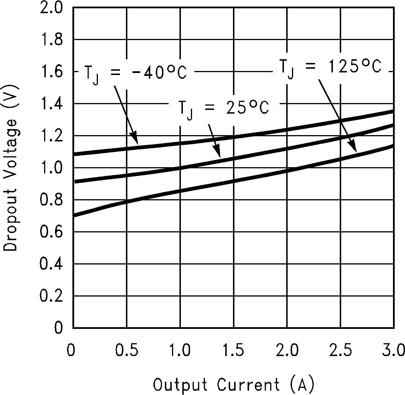
8.2.1.3 Application Curve
8.2.2 Adjustable at 5 V
The application shown in Figure 16 outlines a simple 5 V output application made possible by the LM1085-ADJ. This application can provide 3 A at high efficiencies and very low drop-out.
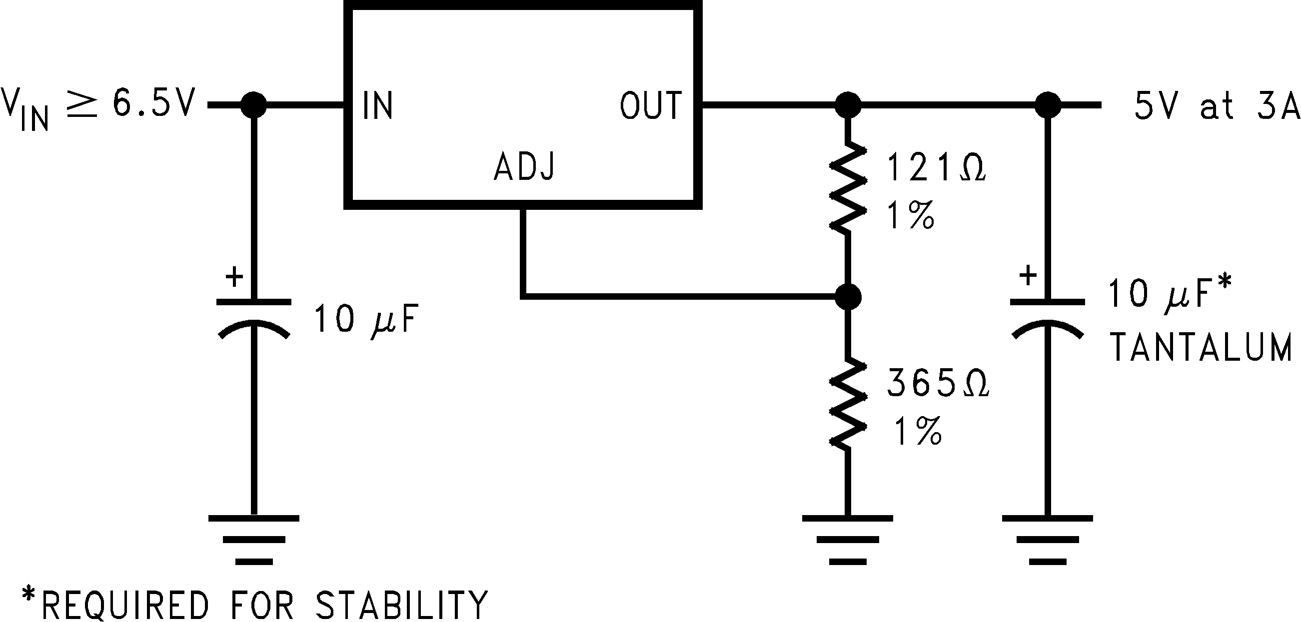 Figure 16. Adjustable @ 5V
8.2.3 5-V Regulator with Shutdown
A variation of the 5 V output regulator application with shutdown control is shown in Figure 17 based on the LM1085-ADJ. It uses a simple NPN transistor on the ADJ pin to block or sink the current on the ADJ pin. If the TTL logic is pulled high, the NPN transistor is activated and the part is disabled, outputting approximately 1.25 V. If the TTL logic is pulled low, the NPN transistor is unbiased and the regulator functions normally.
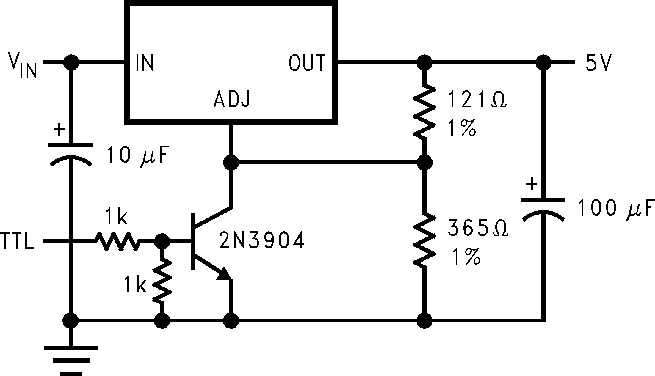 Figure 17. 5-V Regulator with Shutdown
8.2.4 Battery Charger
The LM1085-ADJ can be used as a battery charger to regulate the charging current required by the battery bank as shown in Figure 18. In this application the LM1085 acts as a constant voltage, constant current part by sensing the voltage potential across the battery and compensating it to the current voltage. To maintain this voltage, the regulator delivers the maximum charging current required to charge the battery. As the battery approaches the fully charged state, the potential drop across the sense resistor, RS, reduces and the regulator throttles back the current to maintain the float voltage of the battery.
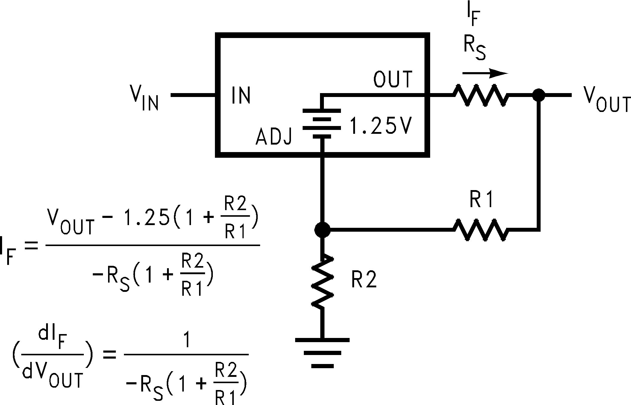 Figure 18. Battery Charger
8.2.5 Adjustable Fixed Regulator
A simple adjustable, fixed range output regulator can be made possible by placing a variable resistor on the ground of the device as shown in Figure 19 based on the fixed output voltage LM1085-5.0. The GND pin has a small quiescent current of 5 mA typical. Increasing the resistance on the GND pin increases the voltage potential across the resistor. This potential is then mirrored on to the output to increase the total output voltage by the potential drop across the GND resistor.
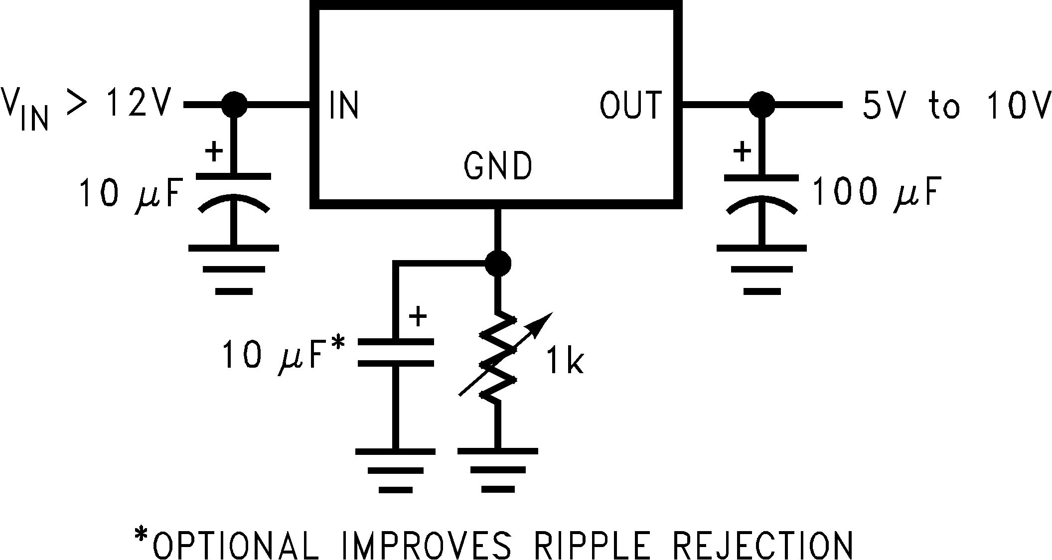 Figure 19. Adjustable Fixed Regulator
8.2.6 Regulator with Reference
A fixed output voltage version of the LM1085-5.0 can be employed to provide an output rail and a reference rail at the same time as shown in Figure 20. This simple application makes use of a reference diode, the LM136-5, to regulate the GND voltage to a fixed 5 V based on the quiescent current generated by the GND pin. This voltage is then added onto the output to generate a total of 10 V out.
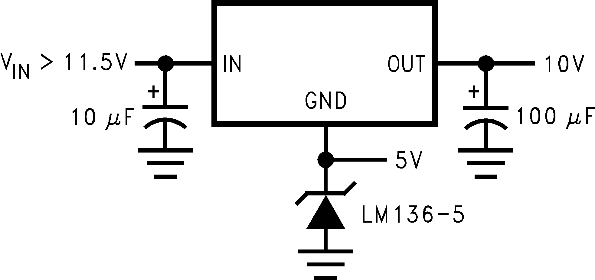 Figure 20. Regulator With Reference
8.2.7 High Current Lamp Driver Protection
A simple constant current source with protection can be designed by controlling the impedance between the lamp and ground. The LM1085-ADJ shown in Figure 21 makes use of an external TTL or CMOS input to drive the NPN transistor. This pulls the output of the regulator to a few tenths of a volt and puts the part into current limit. Releasing the logic will reduce the current flow across the lamp into the normal operating current thereby protecting the lamp during startup.
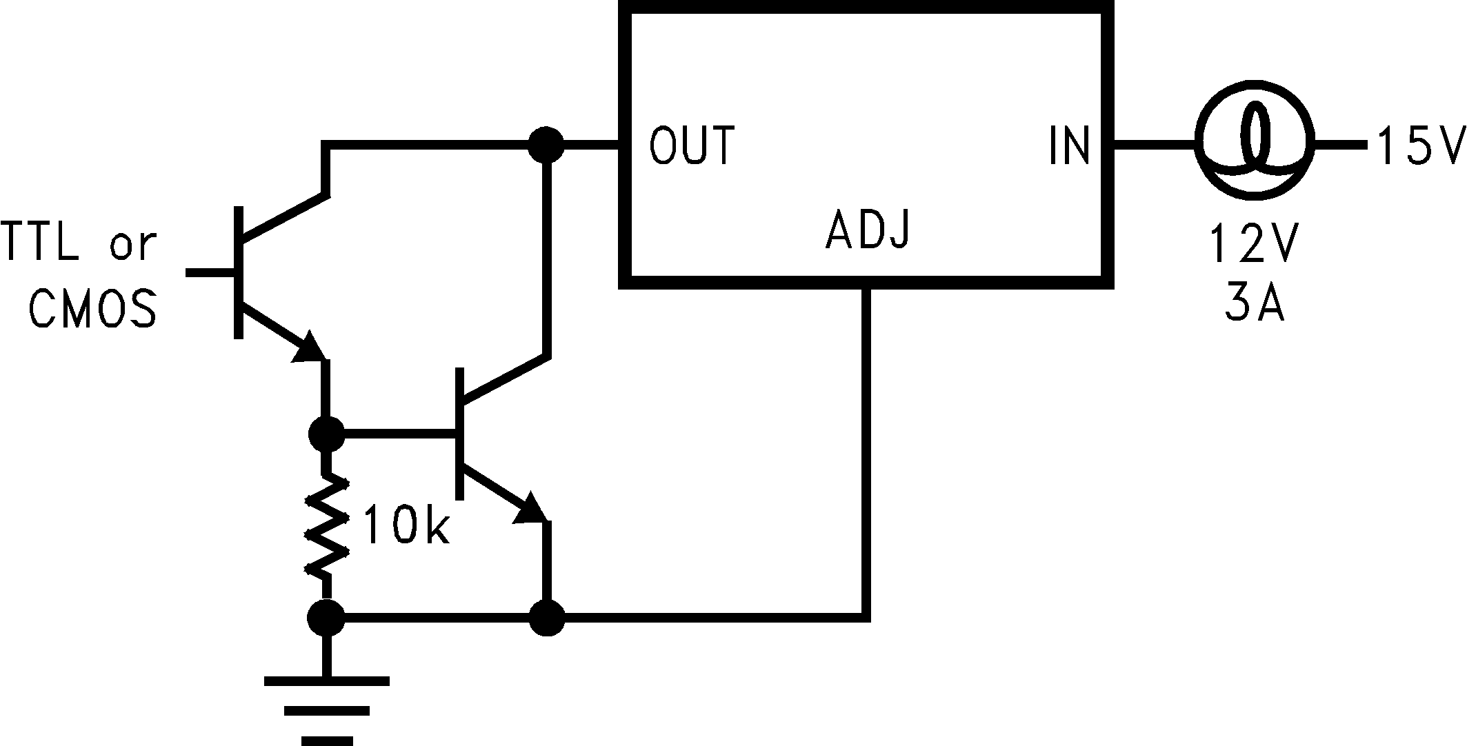 Figure 21. High Current Lamp Driver Protection
8.2.8 Battery Backup Regulated Supply
A regulated battery backup supply can be generated by using two fixed output voltage versions of the part as shown in Figure 22. The top regulator supplies the Line voltage during normal operation, however when the input is not available, the second regulator derives power from the battery backup and regulates it to 5 V based on the LM1085-5.0. The diodes prevent the rails from back feeding into the supply and batteries.
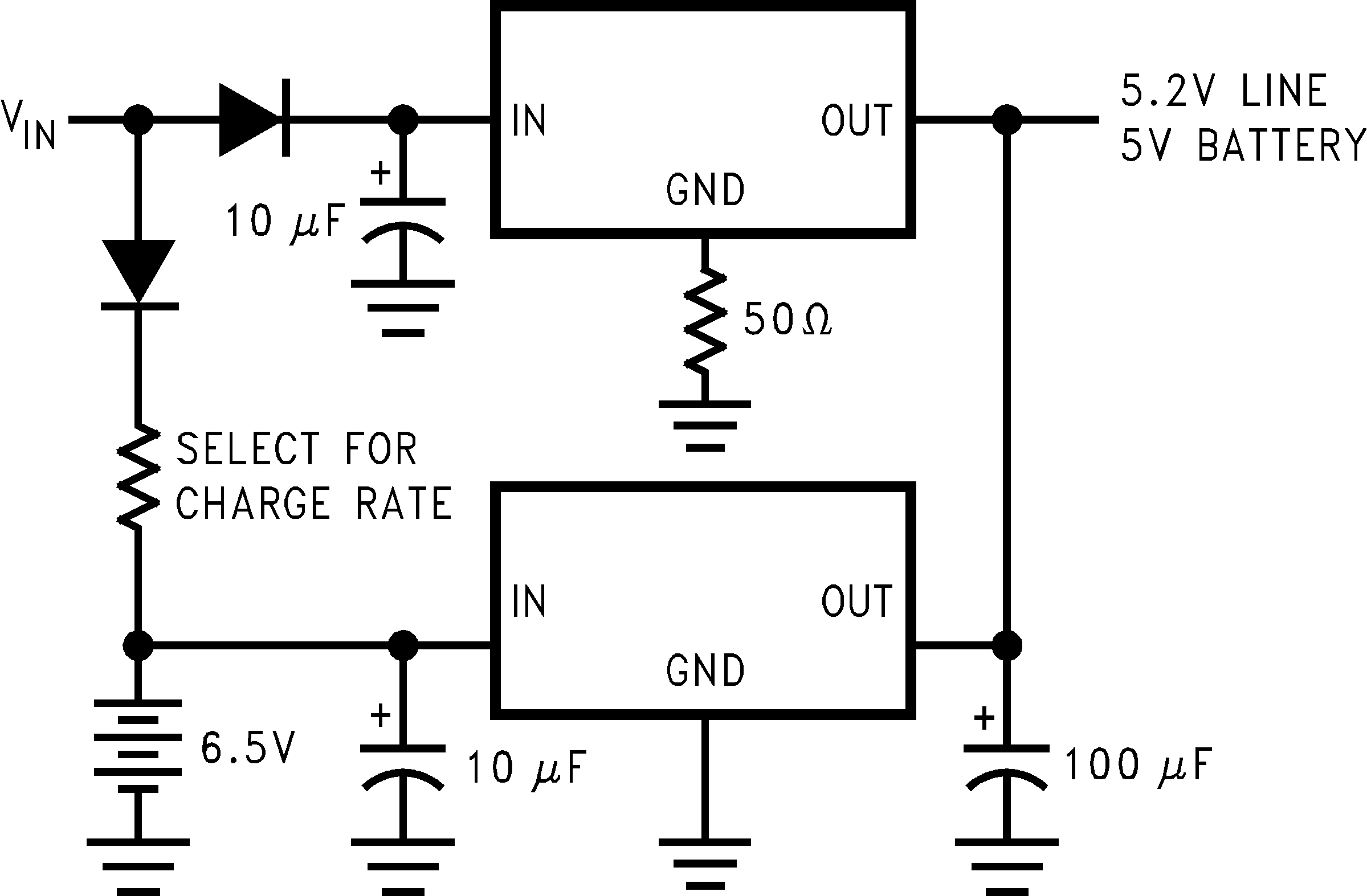 Figure 22. Battery Backup Regulated Supply
8.2.9 Ripple Rejection Enhancement
A very simple ripple rejection circuit is shown in Figure 23 using the LM1085-ADJ. The capacitor C1 smooths out the ripple on the output by cleaning up the feedback path and preventing excess noise from feeding back into the regulator. Please remember XC1 should be approximately equal to R1 at the ripple frequency.
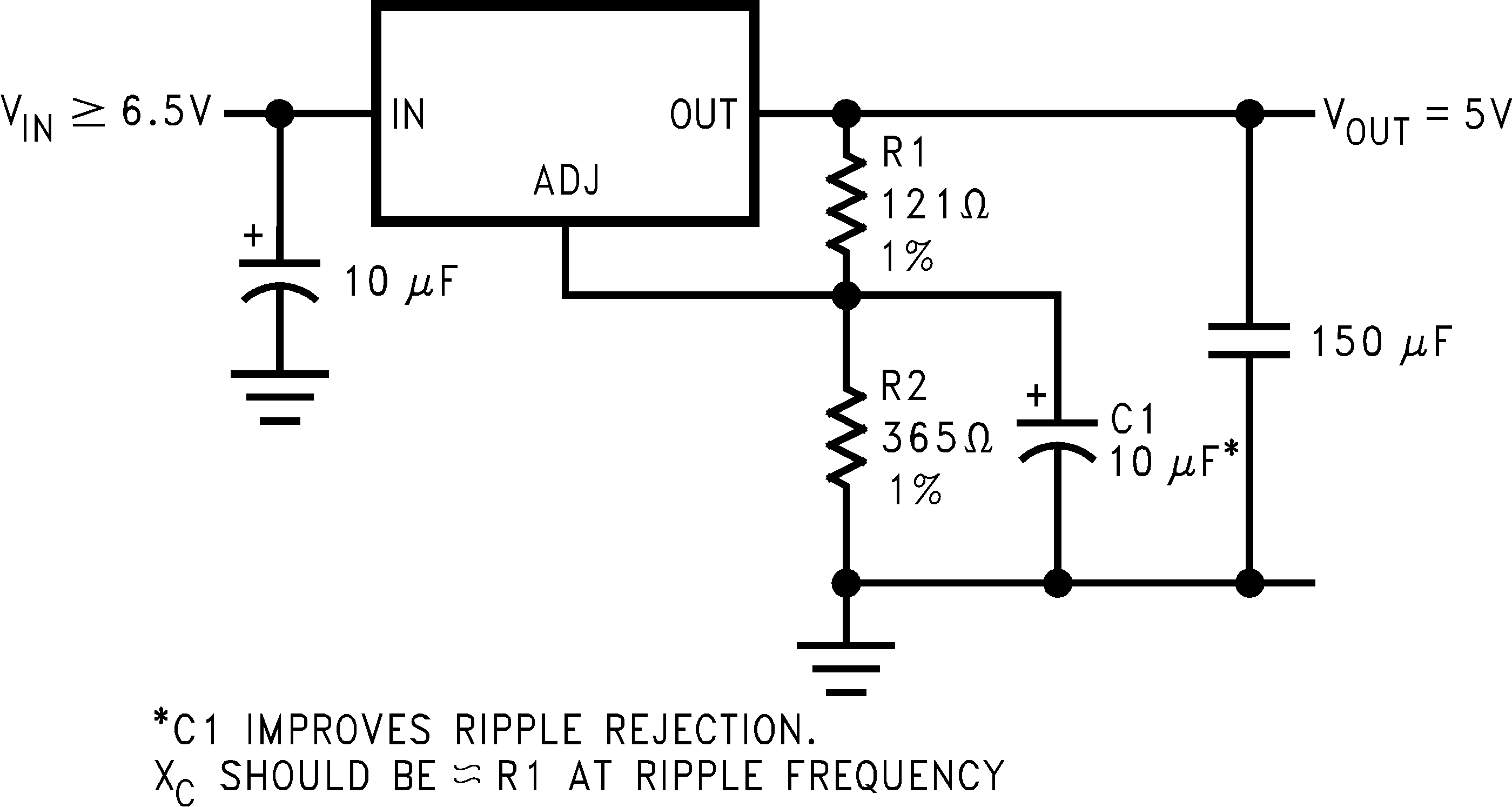 Figure 23. Ripple Rejection Enhancement
8.2.10 Automatic Light Control
A common street light control or automatic light control circuit is designed in Figure 24 based on the LM1085-ADJ. The photo transistor conducts in the presence of light and grounds the ADJ pin preventing the lamp from turning on. However, in the absence of light, the LM1085 regulates the voltage to 1.25V between OUT and ADJ, ensuring the lamp remains on.
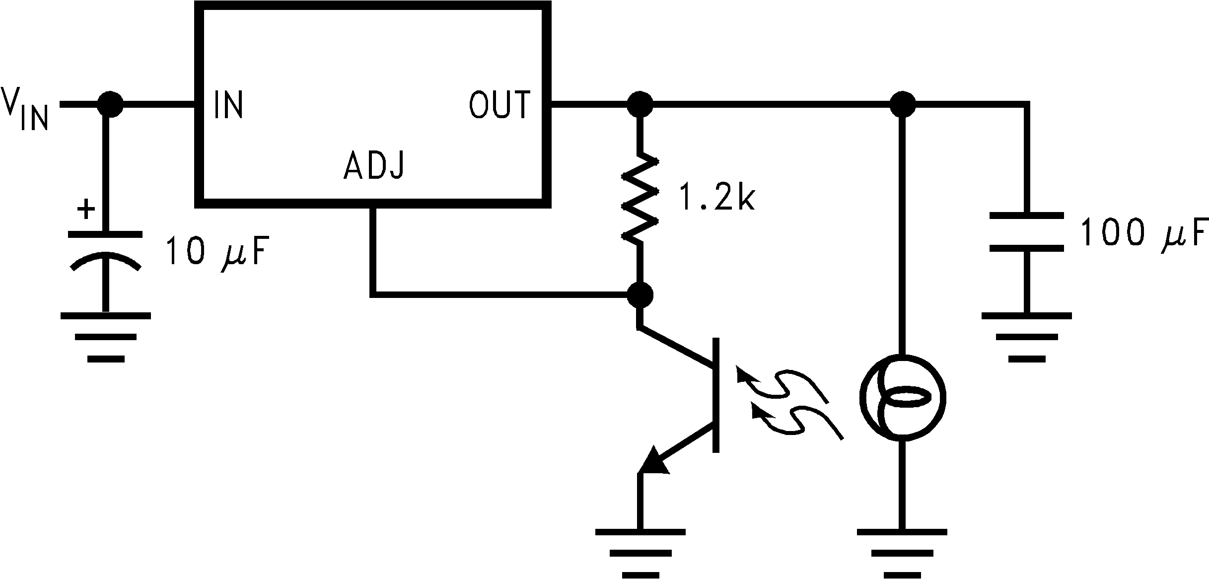 Figure 24. Automatic Light Control
8.2.11 Generating Negative Supply Voltage
A quick inverting output rail or negative output rail is shown in Figure 25 using the LM1085 fixed output part. By tying the output to GND, the GND node is at a relatively more negative potential than the output. This is then interfaced to the negative application such as an operational amplifier or any other rail needing negative voltage.
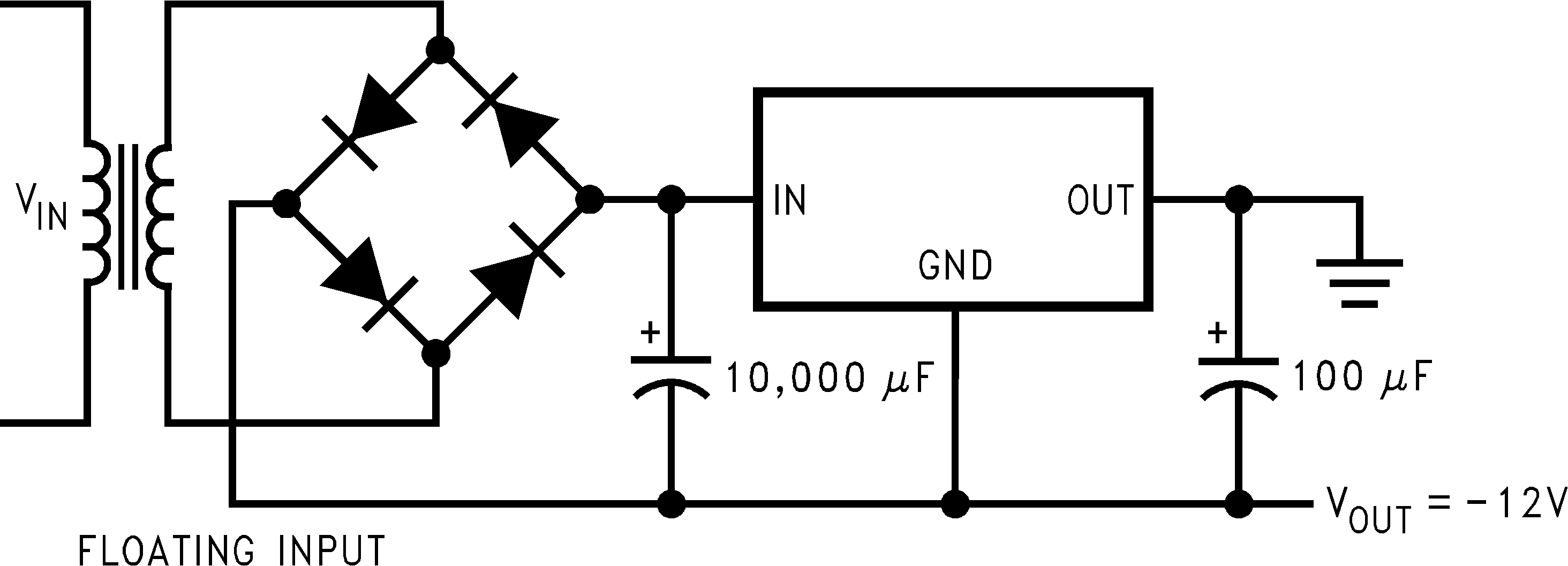 Figure 25. Generating Negative Supply Voltage
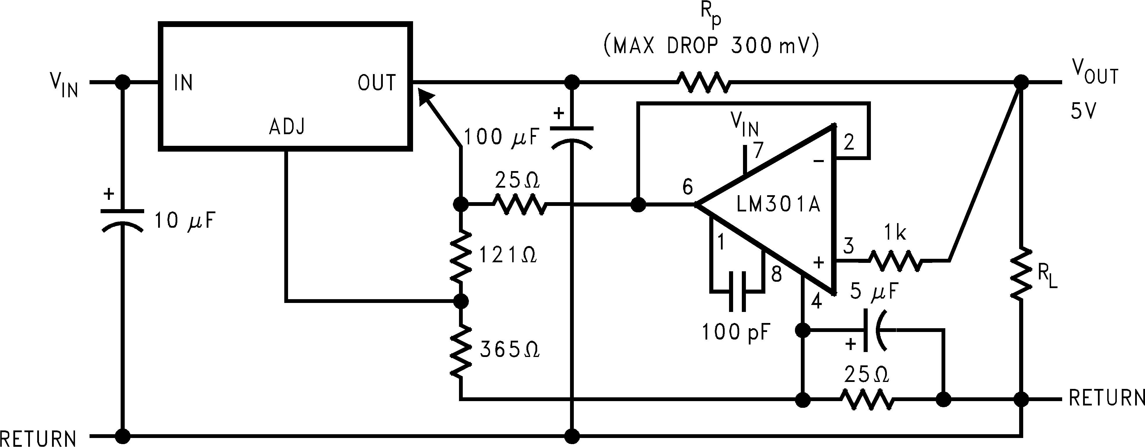
8.2.12 Remote Sensing
Remote sensing is a method of compensating the output voltage to a very precise degree by sensing the output and feeding it back through the feedback. The circuit implementing this is shown in Figure 26 using the LM1085-ADJ. The output of the regulator is fed into a voltage follower to avoid any loading effects and the output of the op-amp is injected into the top of the feedback resistor network. This has the effect of modulating the voltage to a precise degree without additional loading on the output.