SBOS518E May 2011 – April 2015 TMP006
PRODUCTION DATA.
- 1 Features
- 2 Applications
- 3 Description
- 4 Revision History
- 5 Device Comparison Table
- 6 Pin Configuration and Functions
- 7 Specifications
-
8 Detailed Description
- 8.1 Overview
- 8.2 Functional Block Diagram
- 8.3 Feature Description
- 8.4 Device Functional Modes
- 8.5 Register Maps
- 9 Application and Implementation
- 10Power-Supply Recommendations
- 11Layout
- 12Device and Documentation Support
- 13Mechanical, Packaging, and Orderable Information
Package Options
Mechanical Data (Package|Pins)
- YZF|8
Thermal pad, mechanical data (Package|Pins)
Orderable Information
1 Features
- Integrated MEMs Thermopile for Noncontact Temperature Sensing
- Local Temperature Sensor for Cold Junction Reference
- ±1°C (max) from 0°C to 60°C
- ±1.5°C (max) from –40°C to +125°C
- Two-Wire Serial Interface Options:
- I2C and SMBus Compatible
- TMP006 at 3.3 V
- TMP006B at 1.8 V
- Eight Programmable Addresses
- I2C and SMBus Compatible
- Low Power
- Supply: 2.2 V to 5.5 V
- Active Current: 240 μA (typ)
- 1-µA shutdown (max)
- Compact Package
- 1.6-mm × 1.6-mm × 0.625-mm DSBGA
2 Applications
- Noncontact Temperature Sensing
- Case Temperature
- Laser Printers
- Power Relays
- Health and Beauty
- HVAC Comfort Optimization
- Gas Concentration
- Flame Detection
3 Description
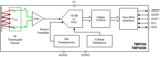
The TMP006 and TMP006B are fully integrated MEMs thermopile sensors that measure the temperature of an object without having to be in direct contact. The thermopile absorbs passive infrared energy from an object at wavelengths between 4 um to 16 um within the end-user defined field of view.
The corresponding change in voltage across the thermopile is digitized and reported with the on-chip die thermal sensor measurement through an I2C- and SMBus-compatible interface. With this data, the target object temperature can be calculated by an external processor.
The TMP007 is an enhanced version of the TMP006 or TMP006B. The TMP007 combines all the features of the TMP006 and TMP006B with an additional math engine to perform all of the equations on chip, allowing the target object temperature to be read directly from the device. The TMP007 also provides built-in nonvolatile memory for storing calibration coefficients.
The Infrared thermopile sensor is specified to operate from –40°C to +125°C. It is possible to measure an object temperature beyond the device operating range as long as the device itself does not exceed the operating temperature range (–40°C to +125°C).
Device Information(1)
| PART NUMBER | PACKAGE | BODY SIZE (NOM) |
|---|---|---|
| TMP006 | DSBGA (8) | 1.60 mm × 1.60 mm |
| TMP006B |
- For all available packages, see the package option addendum at the end of the datasheet.
