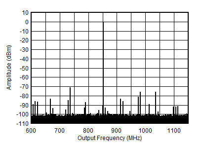
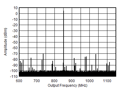
SBASA44B august   2021  – june 2023 AFE7900

PRODUCTION DATA  

  1.   1
  2. 1Features
  3. 2Applications
  4. 3Description
  5. 4Revision History
  6. 5Specifications
    1. 5.1  Absolute Maximum Ratings
    2. 5.2  ESD Ratings
    3. 5.3  Recommended Operating Conditions
    4. 5.4  Thermal Information
    5. 5.5  Transmitter Electrical Characteristics
    6. 5.6  RF ADC Electrical Characteristics
    7. 5.7  PLL/VCO/Clock Electrical Characteristics
    8. 5.8  Digital Electrical Characteristics
    9. 5.9  Power Supply Electrical Characteristics
    10. 5.10 Timing Requirements
    11. 5.11 Switching Characteristics
    12. 5.12 Typical Characteristics
      1. 5.12.1  RX Typical Characteristics 30 MHz and 400 MHz
      2. 5.12.2  RX Typical Characteristics at 800MHz
      3. 5.12.3  RX Typical Characteristics 1.75GHz to 1.9GHz
      4. 5.12.4  RX Typical Characteristics 2.6GHz
      5. 5.12.5  RX Typical Characteristics 3.5GHz
      6. 5.12.6  RX Typical Characteristics 4.9GHz
      7. 5.12.7  TX Typical Characteristics at 30MHz and 400MHz
      8. 5.12.8  TX Typical Characteristics at 800MHz
      9. 5.12.9  TX Typical Characteristics at 1.8GHz
      10. 5.12.10 TX Typical Characteristics at 2.6GHz
      11. 5.12.11 TX Typical Characteristics at 3.5GHz
      12. 5.12.12 TX Typical Characteristics at 4.9GHz
      13. 5.12.13 TX Typical Characteristics at 7.1GHz
      14. 5.12.14 PLL and Clock Typical Characteristics
  7. 6Device and Documentation Support
    1. 6.1 Receiving Notification of Documentation Updates
    2. 6.2 Support Resources
    3. 6.3 Trademarks
    4. 6.4 Electrostatic Discharge Caution
    5. 6.5 Glossary
  8. 7Mechanical, Packaging, and Orderable Information

Package Options

Mechanical Data (Package|Pins)
Thermal pad, mechanical data (Package|Pins)
Orderable Information

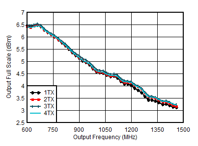
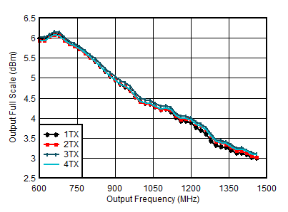
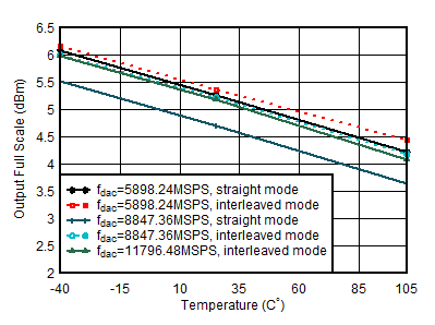
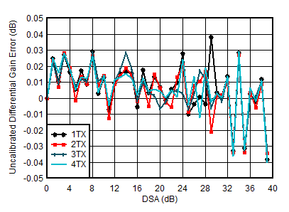
TX Typical Characteristics at 800MHz

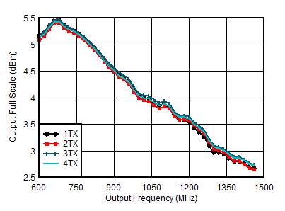
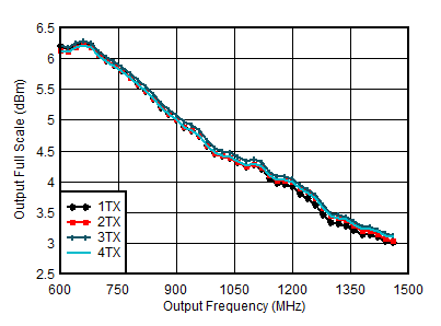
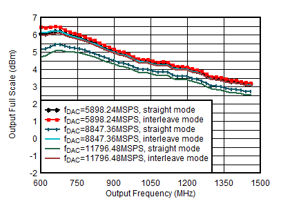
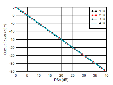
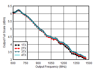
Typical values at TA = +25°C with nominal supplies. Unless otherwise noted, TX input data rate = 491.52MSPS, fDAC = 11796.48MSPS, interleave mode, AOUT = –1 dBFS, 1st Nyquist zone output, Internal PLL, fREF = 491.52MSPS, 24x Interpolation, DSA = 0 dB, Sin(x)/x enabled, DSA calibrated.
GUID-8593C367-418F-4552-AF7A-97C6E3FD0707-low.gif
Including PCB and cable losses, Aout = -0.5dFBS, DSA = 0, 0.8 GHz matching
Figure 5-272 TX Full Scale vs RF Frequency and Channel at 5898.24MSPS, Straight Mode
GUID-337E8EDD-F530-4D50-8451-0E0557A04B55-low.gif
Including PCB and cable losses, Aout = -0.5dFBS, DSA = 0, 0.8 GHz matching
Figure 5-274 TX Full Scale vs RF Frequency and Channel at 5898.24MSPS, Interleave Mode
GUID-68412043-1CAD-4DC1-86D0-3B727191C3BC-low.gif
Including PCB and cable losses, Aout = -0.5dFBS, DSA = 0, 0.8 GHz matching
Figure 5-276 TX Full Scale vs RF Frequency and Channel at 11796.48MSPS, Interleave Mode
GUID-A19949CE-60F2-4281-BCA6-8BC6A538EBC4-low.gif
including PCB and cable losses, Aout = -0.5dFBS, DSA = 0, 0.8 GHz matching
Figure 5-278 TX Output Fullscale vs Temperature
GUID-51D2FA83-286E-4A22-B563-BA5258903DEB-low.gif
fDAC=5898.24MSPS, interleave mode, matching at 0.8 GHz
Differential Gain Error = POUT(DSA Setting – 1) – POUT(DSA Setting) + 1
Figure 5-280 TX Uncalibrated Differential Gain Error vs DSA Setting and Channel at 0.85 GHz
GUID-7E59FA84-617F-4930-A532-D250EACC536B-low.gif
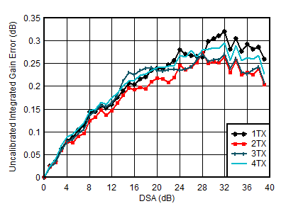
fDAC=5898.24MSPS, interleave mode, matching at 0.8 GHz
Integrated Gain Error = POUT(DSA Setting ) – POUT(DSA Setting = 0) + DSA Settings
Figure 5-282 TX Uncalibrated Integrated Gain Error vs DSA Setting and Channel at 0.85 GHz
GUID-6C2AFDF1-7DE5-45B2-B161-E09753220C0B-low.gif
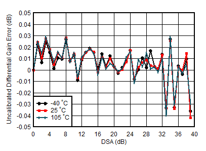
fDAC = 5898.24MSPS, interleave mode, matching at 0.8 GHz
Differential Gain Error = POUT(DSA Setting – 1) – POUT(DSA Setting) + 1
Figure 5-284 TX Uncalibrated Differential Gain Error vs DSA Setting and Temperature at 0.85 GHz
GUID-FE3A3916-4E4F-4DFE-84D0-2E4055480EBF-low.gif
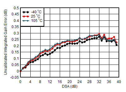
fDAC = 5898.24MSPS, interleave mode, matching at 0.8 GHz
Integrated Gain Error = POUT(DSA Setting ) – POUT(DSA Setting = 0) + DSA Setting
Figure 5-286 TX Uncalibrated Integrated Gain Error vs DSA Setting and Temperature at 0.85 GHz
GUID-B8F92EA2-EB64-4FB6-9FE8-88FB271F8027-low.gif
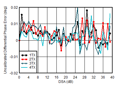
fDAC = 5898.24MSPS, interleave mode, matching at 0.8 GHz
Differential Phase Error = PhaseOUT(DSA Setting – 1) – PhaseOUT(DSA Setting)
Figure 5-288 TX Uncalibrated Differential Phase Error vs DSA Setting and Channel at 0.85 GHz
GUID-0FAE4550-BFCE-461C-A0DA-5C611845D805-low.gif
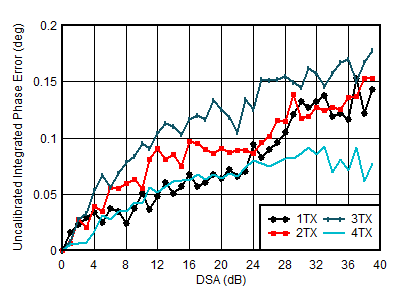
fDAC = 5898.24MSPS, interleave mode, matching at 0.8 GHz
Integrated Phase Error = PhaseOUT(DSA Setting) – PhaseOUT(DSA Setting = 0)
Figure 5-290 TX Uncalibrated Integrated Phase Error vs DSA Setting and Channel at 0.85 GHz
GUID-EA0DD7D8-B305-4736-85E8-5808BC16D1F8-low.gif
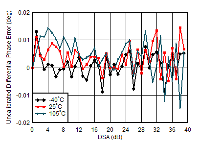
fDAC = 5898.24MSPS, interleave mode, matching at 0.8 GHz
Differential Phase Error = PhaseOUT(DSA Setting – 1) – PhaseOUT(DSA Setting) + 1
Figure 5-292 TX Uncalibrated Differential Phase Error vs DSA Setting and Temperature at 0.85 GHz
GUID-4BDF704F-AA2E-4918-8BF2-47DC365331C1-low.gif
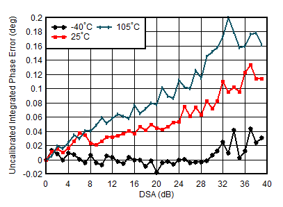
fDAC = 5898.24MSPS, interleave mode, matching at 0.8 GHz
Integrated Phase Error = PhaseOUT(DSA Setting) – PhaseOUT(DSA Setting = 0)
Figure 5-294 TX Uncalibrated Integrated Phase Error vs DSA Setting and Temperature at 0.85 GHz
GUID-1DF06F1E-7260-4FBA-AAA0-2F4760788E81-low.gif
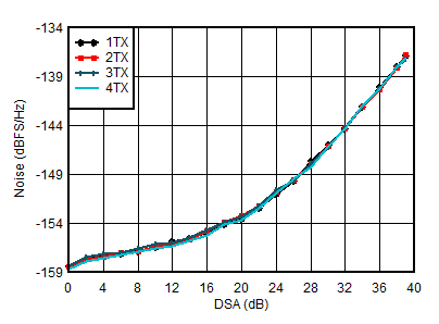
fDAC = 5898.24MSPS, interleave mode, matching at 0.8 GHz, POUT = –13 dBFS
Figure 5-296 TX Output Noise vs Channel and Attenuation at 0.85 GHz
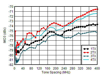
GUID-41F434DA-D836-41AD-B8EF-25F47AD1D7D2-low.gif
fDAC = 5898.24MSPS, straight mode, fCENTER = 0.85 GHz, matching at 0.8 GHz, –13 dBFS each tone
Figure 5-298 TX IMD3 vs Tone Spacing and Channel at 0.85 GHz
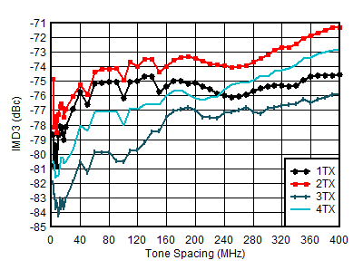
GUID-9B20ED0C-7134-49EE-9B1E-A5AF3858AD60-low.gif
fDAC = 11796.48MSPS, interleave mode, fCENTER = 0.85 GHz, matching at 0.8 GHz, –13 dBFS each tone
Figure 5-300 TX IMD3 vs Tone Spacing and Channel at 0.85 GHz
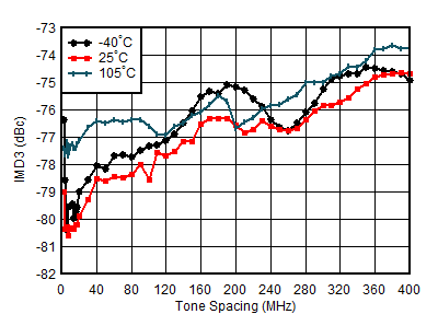
GUID-D928C372-04F7-4413-8908-B2315DE76EAF-low.gif
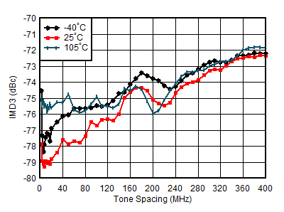
fDAC = 8847.36MSPS, straight mode, fCENTER =0.85 GHz, matching at 0.8 GHz, –13 dBFS each tone, worst channel
Figure 5-302 TX IMD3 vs Tone Spacing and Temperature at 0.85 GHz
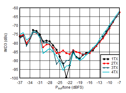
GUID-76B0B823-4441-4513-9F87-046616240DAA-low.gif
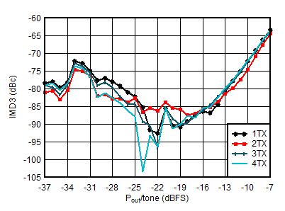
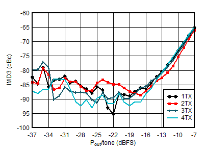
fDAC = 5898.24MSPS, straight mode, fCENTER = 0.85 GHz, fSPACING = 20 MHz, matching at 0.8 GHz
Figure 5-304 TX IMD3 vs Digital Level at 0.85 GHz
GUID-E2DFFB67-ACD7-4169-8CE4-ABA7544D058C-low.gif
fDAC = 11796.48MSPS, interleave mode, fCENTER = 0.85 GHz, fSPACING = 20 MHz, matching at 0.8 GHz
Figure 5-306 TX IMD3 vs Digital Level at 0.85 GHz
GUID-DC02F8C6-A825-487E-BE1B-B59443DD23E0-low.gif
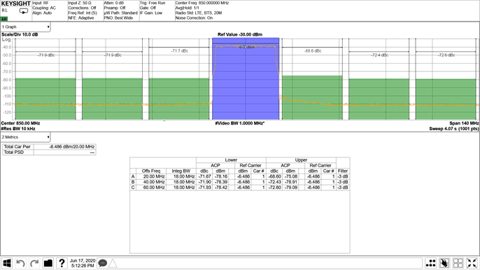
TM1.1, POUT_RMS = –13 dBFS
Figure 5-308 TX 20-MHz LTE Output Spectrum at 0.85 GHz
GUID-EAF95571-E1F7-4F97-A74F-BC6B3240F94B-low.gif
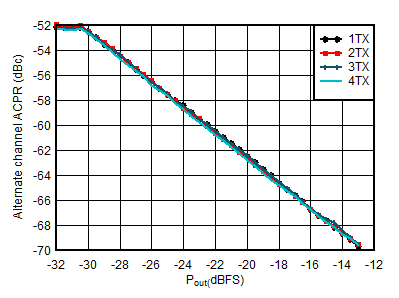
Matching at 0.8 GHz, single carrier 20-MHz BW TM1.1 LTE
Figure 5-310 TX 20-MHz LTE alt-ACPR vs Digital Level at 0.85 GHz
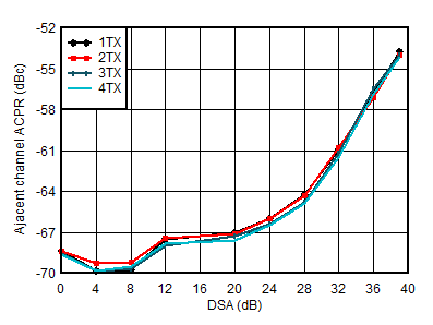
GUID-8A55779B-AAF0-436C-8DA3-853E35865BBC-low.gif
Matching at 0.8 GHz, single carrier 20-MHz BW TM1.1 LTE
Figure 5-312 TX 20-MHz LTE ACPR vs DSA at 0.85 GHz
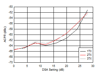
GUID-3DB4C739-162B-42D1-8970-FF385D15DBBE-low.gif
Matching at 0.8 GHz, single carrier 100-MHz BW TM1.1 NR
Figure 5-314 TX 100-MHz NR ACPR vs DSA at 0.85 GHz
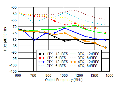
GUID-FC71DB63-99B4-4063-9BB9-C45BEA79E4E2-low.gif
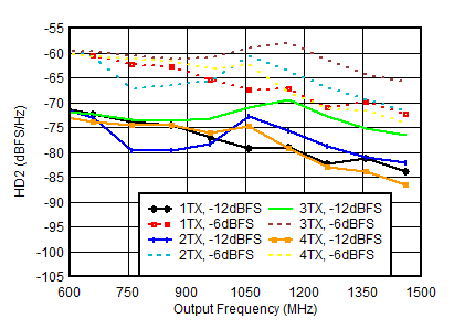
Matching at 0.8 GHz, fDAC = 5898.24GSPS, straight mode
Figure 5-316 TX HD2 vs Digital Amplitude and Output Frequency at 0.85 GHz
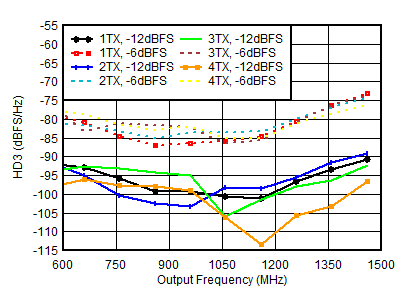
GUID-283309F7-DBA9-431A-976A-F0FED804D7BA-low.gif
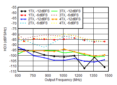
Matching at 0.8 GHz, fDAC = 5898.24MSPS, straight mode, normalized to output power at harmonic frequency
Figure 5-318 TX HD3 vs Digital Amplitude and Output Frequency at 0.85 GHz
GUID-700809DA-8343-41BC-9A8E-CD1E50BF9802-low.gif
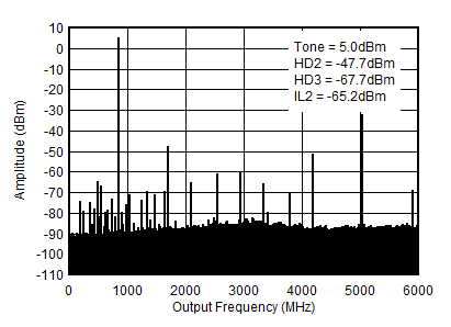
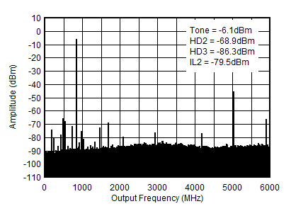
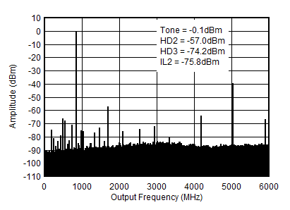
fDAC = 5898.24MSPS, interleave mode, 0.8 GHz matching, includes PCB and cable losses. ILn = fS/n ± fOUT.
Figure 5-320 TX Single Tone (–12 dBFS) Output Spectrum at 0.85 GHz (0-fDAC)
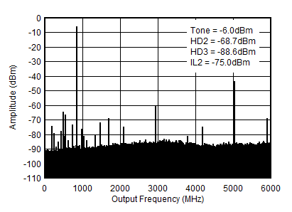
GUID-92A1C74B-35FE-4AB0-8F33-1FD096406D6D-low.gif
fDAC = 5898.24MSPS, interleave mode, 0.8 GHz matching, includes PCB and cable losses. ILn = fS/n ± fOUT.
Figure 5-322 TX Single Tone (–6 dBFS) Output Spectrum at 0.85 GHz (0-fDAC)
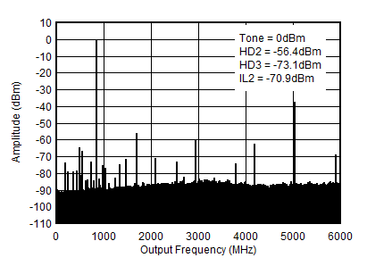
GUID-D88EB4A4-6745-43F6-A1ED-5431A53A31BC-low.gif
fDAC = 5898.24MSPS, interleave mode, 0.8 GHz matching, includes PCB and cable losses. ILn = fS/n ± fOUT.
Figure 5-324 TX Single Tone (–1 dBFS) Output Spectrum at 0.85 GHz (0-fDAC)
GUID-1942DA41-4A95-44F2-8B68-9874331DF70E-low.gif
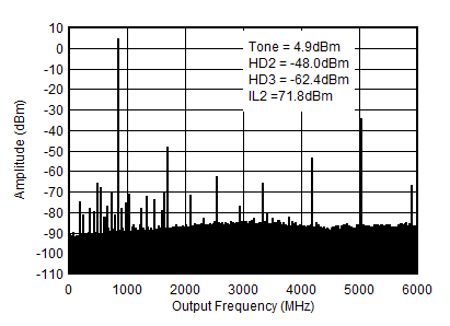
fDAC = 5898.24MSPS, straight mode, 0.8 GHz matching, includes PCB and cable losses. ILn = fS/n ± fOUT and is due to mixing with digital clocks.
Figure 5-326 TX Single Tone (–12 dBFS) Output Spectrum at 0.85 GHz (0-fDAC)
GUID-2D821757-4DD7-4255-A0D4-433B7283C2F7-low.gif
fDAC = 5898.24MSPS, straight mode, 0.8 GHz matching, includes PCB and cable losses. ILn = fS/n ± fOUT and is due to mixing with digital clocks.
Figure 5-328 TX Single Tone (–6 dBFS) Output Spectrum at 0.85 GHz (0-fDAC)
GUID-9385E35D-7FD2-4278-B9DC-03369D02549A-low.gif
fDAC = 5898.24MSPS, straight mode, 0.8 GHz matching, includes PCB and cable losses. ILn = fS/n ± fOUT and is due to mixing with digital clocks.
Figure 5-330 TX Single Tone (–1 dBFS) Output Spectrum at 0.85 GHz (0-fDAC)
GUID-373BC9CA-CAFA-431F-93D8-64D360EDF072-low.gif
Including PCB and cable losses, Aout = -0.5dFBS, DSA = 0, 0.8 GHzmatching
Figure 5-273 TX Full Scale vs RF Frequency and Channel at 8847.36MSPS, Straight Mode
GUID-08FCD338-D528-4C1C-BA11-1AF86869B7F8-low.gif
Including PCB and cable losses, Aout = -0.5dFBS, DSA = 0, 0.8 GHz matching
Figure 5-275 TX Full Scale vs RF Frequency and Channel at 8847.36MSPS, Interleave Mode
GUID-2FBEE87F-D85A-4BD0-A248-223CCD66F880-low.gif
including PCB and cable losses, Aout = -0.5dFBS, DSA = 0, 0.8 GHz matching
Figure 5-277 TX Output Fullscale vs Output Frequency
GUID-0550ECFD-7A26-488B-B549-1989A50A59F9-low.gif
fDAC = 11796.48 MSPS, interleave mode, Aout = -0.5dFBS, matching 0.8 GHz
Figure 5-279 TX Output Power vs DSA Setting and Channel at 0.85 GHz
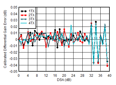
GUID-F476B19C-D773-40B2-8CEE-05329AA80C2F-low.gif
fDAC=5898.24MSPS, interleave mode, matching at 0.8 GHz
Differential Gain Error = POUT(DSA Setting – 1) – POUT(DSA Setting) + 1
Figure 5-281 TX Calibrated Differential Gain Error vs DSA Setting and Channel at 0.85 GHz
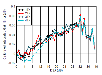
GUID-990C29FC-D635-441E-A020-8255EB9E5D49-low.gif
fDAC=5898.24MSPS, interleave mode, matching at 0.8 GHz
Integrated Gain Error = POUT(DSA Setting ) – POUT(DSA Setting = 0) + DSA Setting
Figure 5-283 TX Calibrated Integrated Gain Error vs DSA Setting and Channel at 0.85 GHz
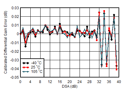
GUID-FD3E5CF0-A88C-40D8-90D1-BA1D610AF492-low.gif
fDAC = 5898.24MSPS, interleave mode, matching at 0.8 GHz
Differential Gain Error = POUT(DSA Setting – 1) – POUT(DSA Setting) + 1
Figure 5-285 TX Calibrated Differential Gain Error vs DSA Setting and Temperature at 0.85 GHz
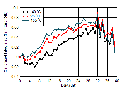
GUID-D74C66ED-18B3-4751-9F7C-B79C45836639-low.gif
fDAC = 5898.24MSPS, interleave mode, matching at 0.8 GHz
Integrated Gain Error = POUT(DSA Setting ) – POUT(DSA Setting = 0) + DSA Setting
Figure 5-287 TX Calibrated Integrated Gain Error vs DSA Setting and Temperature at 0.85 GHz
GUID-44835A38-0B6F-4E36-8B88-55F55A93D75E-low.gif
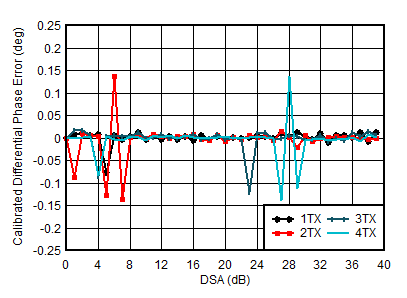
fDAC = 5898.24MSPS, interleave mode, matching at 0.8 GHz
Differential Phase Error = PhaseOUT(DSA Setting – 1) – PhaseOUT(DSA Setting)
Phase DNL spike may occur at any DSA setting.
Figure 5-289 TX Calibrated Differential Phase Error vs DSA Setting and Channel at 0.85 GHz
GUID-C7D3D7EE-B80C-4E51-9398-AB3018A25038-low.gif
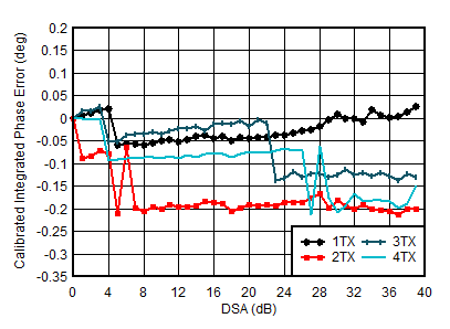
fDAC = 5898.24MSPS, interleave mode, matching at 0.8 GHz
Integrated Phase Error = PhaseOUT(DSA Setting) – PhaseOUT(DSA Setting = 0)
Figure 5-291 TX Calibrated Integrated Phase Error vs DSA Setting and Channel at 0.85 GHz
GUID-BB89A362-A3EA-4D1F-88FC-64DF09B8269C-low.gif
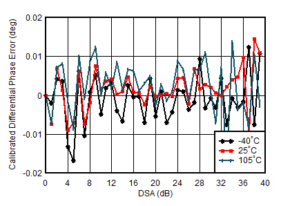
fDAC = 5898.24MSPS, interleave mode, matching at 0.8 GHz, channel with the median variation over DSA setting at 25°C
Differential Phase Error = PhaseOUT(DSA Setting – 1) – PhaseOUT(DSA Setting) + 1
Figure 5-293 TX Calibrated Differential Phase Error vs DSA Setting and Temperature at 0.85 GHz
GUID-FE215174-07C3-42DE-8827-1B4FC0AA623A-low.gif
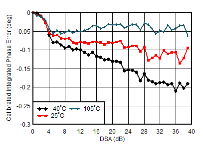
fDAC = 5898.24MSPS, interleave mode, matching at 0.8 GHz
Integrated Phase Error = PhaseOUT(DSA Setting) – PhaseOUT(DSA Setting = 0)
Figure 5-295 TX Calibrated Integrated Phase Error vs DSA Setting and Temperature at 0.85 GHz
GUID-5E2C76F8-25D7-49B3-AF29-FAC60C613BA5-low.gif
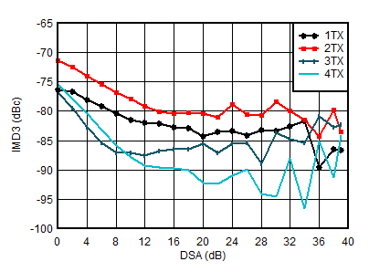
fDAC = 11796.48MSPS, interleave mode, fCENTER = 0.85 GHz, matching at 0.8 GHz, –13 dBFS each tone
Figure 5-297 TX IMD3 vs DSA Setting at 0.85 GHz
GUID-CE9DE1F5-0A6A-4F2B-A754-3C772BFEA0ED-low.gif
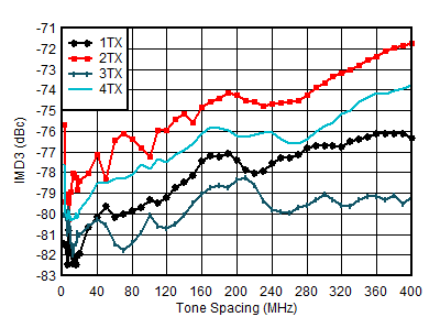
fDAC = 8847.36MSPS, straight mode, fCENTER = 0.85 GHz, matching at 0.8 GHz, –13 dBFS each tone
Figure 5-299 TX IMD3 vs Tone Spacing and Channel at 0.85 GHz
GUID-88BB5553-B5D9-41BE-BC81-0C6FDD6E49F9-low.gif
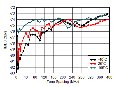
fDAC = 5898.24MSPS, straight mode, fCENTER =0.85 GHz, matching at 0.8 GHz, –13 dBFS each tone, worst channel
Figure 5-301 TX IMD3 vs Tone Spacing and Temperature at 0.85 GHz
GUID-0D323C57-C2D2-456C-8D37-D99FE3BF8E15-low.gif
fDAC = 11796.48MSPS, straight mode, fCENTER =0.85 GHz, matching at 0.8 GHz, –13 dBFS each tone, worst channel
Figure 5-303 TX IMD3 vs Tone Spacing and Temperature at 0.85 GHz
GUID-95EB44FA-4C1C-448A-95BF-47843E32064C-low.gif
fDAC = 8847.36MSPS, straight mode, fCENTER = 0.85 GHz, fSPACING = 20 MHz, matching at 0.8 GHz
Figure 5-305 TX IMD3 vs Digital Level at 0.85 GHz
GUID-5B664E32-4154-4E63-B206-15FAE6F0B788-low.gif
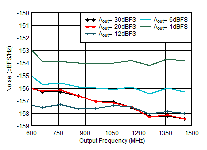
Matching at 0.8 GHz, Single tone, fDAC = 11.79648GSPS, interleave mode, 40-MHz offset, DSA = 0dB
Figure 5-307 TX Single Tone Output Noise vs Frequency and Amplitude at 0.85 GHz
GUID-E1A5457F-D7AB-4F57-B089-EB12DE45B67E-low.gif
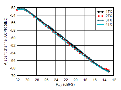
Matching at 0.8 GHz, single carrier 20-MHz BW TM1.1 LTE
Figure 5-309 TX 20-MHz LTE ACPR vs Digital Level at 0.85 GHz
GUID-AA962DE0-8818-4BD7-ADFA-F9344CB60323-low.gif
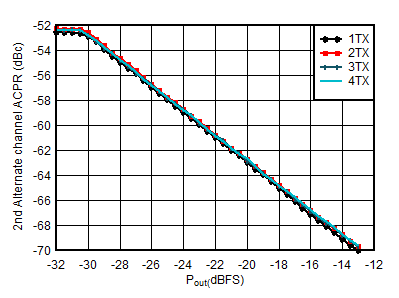
Matching at 0.8 GHz, single carrier 20-MHz BW TM1.1 LTE
Figure 5-311 TX 20-MHz LTE alt2-ACPR vs Digital Level at 0.85 GHz
GUID-ABDBB3ED-819B-46C7-A5E7-428AB2048589-low.gif
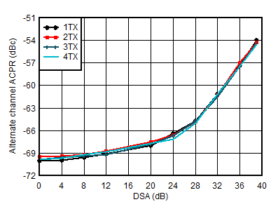
Matching at 0.8 GHz, single carrier 20-MHz BW TM1.1 LTE
Figure 5-313 TX 20-MHz LTE alt-ACPR vs DSA at 0.85 GHz
GUID-2995C91B-D8D3-4358-8CDF-C4E2E1F3F06B-low.gif
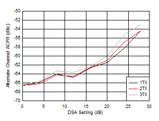
Matching at 0.8 GHz, single carrier 100-MHz BW TM1.1 NR
Figure 5-315 TX 100-MHz NR alt-ACPR vs DSA at 0.85 GHz
GUID-81469047-F6D0-4DE4-8B48-369483C00DDA-low.gif
Matching at 0.8 GHz, fDAC = 8847.36GSPS, straight mode
Figure 5-317 TX HD2 vs Digital Amplitude and Output Frequency at 0.85 GHz
GUID-C3B7E6B9-F7AE-4148-A77E-B42C3529F050-low.gif
Matching at 0.8 GHz, fDAC = 8847.36MSPS, straight mode, normalized to output power at harmonic frequency
Figure 5-319 TX HD3 vs Digital Amplitude and Output Frequency at 0.85 GHz
GUID-637E513A-E6DF-4DF7-BE24-7981CC8BA4FA-low.gif
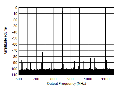
fDAC = 5898.24MSPS, interleave mode, 0.8 GHz matching, includes PCB and cable losses
Figure 5-321 TX Single Tone (–12 dBFS) Output Spectrum at 0.85 GHz (±300 MHz)
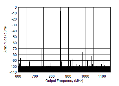
GUID-5CCE8A6C-54BF-4226-B891-05AFCF2AE101-low.gif
fDAC = 5898.24MSPS, interleave mode, 0.8 GHz matching, includes PCB and cable losses
Figure 5-323 TX Single Tone (–6 dBFS) Output Spectrum at 0.85 GHz (±300 MHz)
GUID-91C14DA1-083D-4125-B3A3-005D1B982276-low.gif
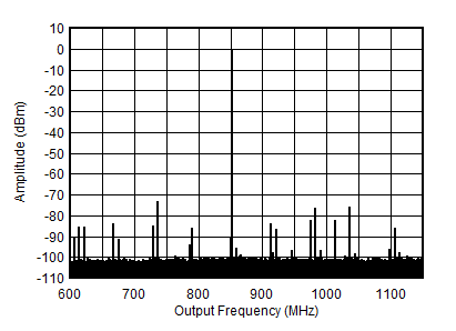
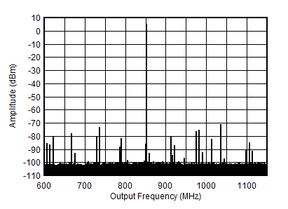
fDAC = 5898.24MSPS, interleave mode, 0.8 GHz matching, includes PCB and cable losses
Figure 5-325 TX Single Tone (–1 dBFS) Output Spectrum at 0.85 GHz (±300 MHz)
GUID-27EA1ADC-4F4B-4912-8CB2-1A3466D85566-low.gif
fDAC = 5898.24MSPS, straight mode, 0.8 GHz matching, includes PCB and cable losses
Figure 5-327 TX Single Tone (–12 dBFS) Output Spectrum at 0.85 GHz (±300 MHz)
GUID-870BD815-D715-479D-A638-D438BD0874C2-low.gif
fDAC = 5898.24MSPS, straight mode, 0.8 GHz matching, includes PCB and cable losses
Figure 5-329 TX Single Tone (–6 dBFS) Output Spectrum at 0.85 GHz (±300 MHz)
GUID-0AB9A5D5-C82D-4779-8D44-EC7E020A6D95-low.gif
fDAC = 5898.24MSPS, straight mode, 0.8 GHz matching, includes PCB and cable losses
Figure 5-331 TX Single Tone (–1 dBFS) Output Spectrum at 0.85 GHz (±300 MHz)