SLUS606P June 2004 – November 2015
PRODUCTION DATA.
- 1 Features
- 2 Applications
- 3 Description
- 4 Revision History
- 5 Device Options
- 6 Pin Configuration and Functions
- 7 Specifications
-
8 Detailed Description
- 8.1 Overview
- 8.2 Functional Block Diagram
- 8.3
Feature Description
- 8.3.1 PWM Controller
- 8.3.2 Temperature Qualification
- 8.3.3 Battery Preconditioning (Precharge)
- 8.3.4 Battery Charge Current
- 8.3.5 Battery Voltage Regulation
- 8.3.6 Charge Termination and Recharge
- 8.3.7 Sleep Mode
- 8.3.8 Charge Status Outputs
- 8.3.9 PG Output
- 8.3.10 CE Input (Charge Enable)
- 8.3.11 Timer Fault Recovery
- 8.3.12 Output Overvoltage Protection (Applies to All Versions)
- 8.3.13 Functional Description For System-Controlled Version (bq2411x)
- 8.3.14 Precharge and Fast-Charge Control
- 8.3.15 Charge Termination and Safety Timers
- 8.3.16 Battery Detection
- 8.3.17 Current Sense Amplifier
- 8.4 Device Functional Modes
- 9 Application and Implementation
- 10Power Supply Recommendations
- 11Layout
- 12Device and Documentation Support
- 13Mechanical, Packaging, and Orderable Information
Package Options
Mechanical Data (Package|Pins)
- RHL|20
Thermal pad, mechanical data (Package|Pins)
- RHL|20
Orderable Information
1 Features
- Ideal For Highly Efficient Charger Designs For Single-, Two-, or Three-Cell Li-Ion and Li-Polymer Battery Packs
- bq24105 Also for LiFePO4 Battery (see Using bq24105 to Charge the LiFePO4 Battery)
- Integrated Synchronous Fixed-Frequency PWM Controller Operating at 1.1 MHz With 0% to 100% Duty Cycle
- Integrated Power FETs for Up To 2-A Charge Rate
- High-Accuracy Voltage and Current Regulation
- Available in Both Stand-Alone (Built-In Charge Management and Control) and System-Controlled (Under System Command) Versions
- Status Outputs for LED or Host Processor Interface Indicates Charge-In-Progress, Charge Completion, Fault, and AC-Adapter Present Conditions
- 20-V Maximum Voltage Rating on IN and OUT Pins
- High-Side Battery Current Sensing
- Battery Temperature Monitoring
- Automatic Sleep Mode for Low Power Consumption
- System-Controlled Version Can Be Used in NiMH and NiCd Applications
- Reverse Leakage Protection Prevents Battery Drainage
- Thermal Shutdown and Protection
- Built-In Battery Detection
- Available in 20-Pin, 3.50 mm × 4.50 mm VQFN Package
2 Applications
- Handheld Products
- Portable Media Players
- Industrial and Medical Equipment
- Portable Equipment
3 Description
The bqSWITCHER™ series are highly integrated Li-ion and Li-polymer switch-mode charge management devices targeted at a wide range of portable applications. The bqSWITCHER™ series offers integrated synchronous PWM controller and power FETs, high-accuracy current and voltage regulation, charge preconditioning, charge status, and charge termination, in a small, thermally enhanced VQFN package. The system-controlled version provides additional inputs for full charge management under system control.
The bqSWITCHER™ charges the battery in three phases: conditioning, constant current, and constant voltage. Charge is terminated based on user- selectable minimum current level. A programmable charge timer provides a safety backup for charge termination. The bqSWITCHER™ automatically restarts the charge cycle if the battery voltage falls below an internal threshold. The bqSWITCHER™ automatically enters sleep mode when VCC supply is removed.
Device Information (1)
| PART NUMBER | PACKAGE | BODY SIZE (NOM) |
|---|---|---|
| bq241xx | VQFN (20) | 3.50 mm × 4.50 mm |
- For all available packages, see the orderable addendum at the end of the data sheet.
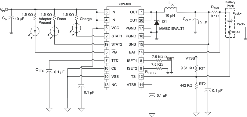
Typical 1-Cell Application
