SLUSB20C November 2012 – November 2021
PRODUCTION DATA
- 1 Features
- 2 Applications
- 3 Description
- 4 Revision History
- 5 Device Comparison Table
- 6 Pin Configuration and Functions
-
7 Specifications
- 7.1 Absolute Maximum Ratings
- 7.2 ESD Ratings
- 7.3 Recommended Operating Conditions
- 7.4 Thermal Information
- 7.5 Electrical Characteristics: Supply Current
- 7.6 Digital Input and Output DC Characteristics
- 7.7 Power-on Reset
- 7.8 2.5-V LDO Regulator
- 7.9 Internal Clock Oscillators
- 7.10 ADC (Temperature and Cell Measurement) Characteristics
- 7.11 Integrating ADC (Coulomb Counter) Characteristics
- 7.12 Data Flash Memory Characteristics
- 7.13 I2C-Compatible Interface Communication Timing Requirements
- 7.14 Typical Characteristics
- 8 Detailed Description
- 9 Application and Implementation
- 10Power Supply Recommendations
- 11Layout
- 12Device and Documentation Support
- 13Mechanical, Packaging, and Orderable Information
Package Options
Mechanical Data (Package|Pins)
- YZF|15
Thermal pad, mechanical data (Package|Pins)
Orderable Information
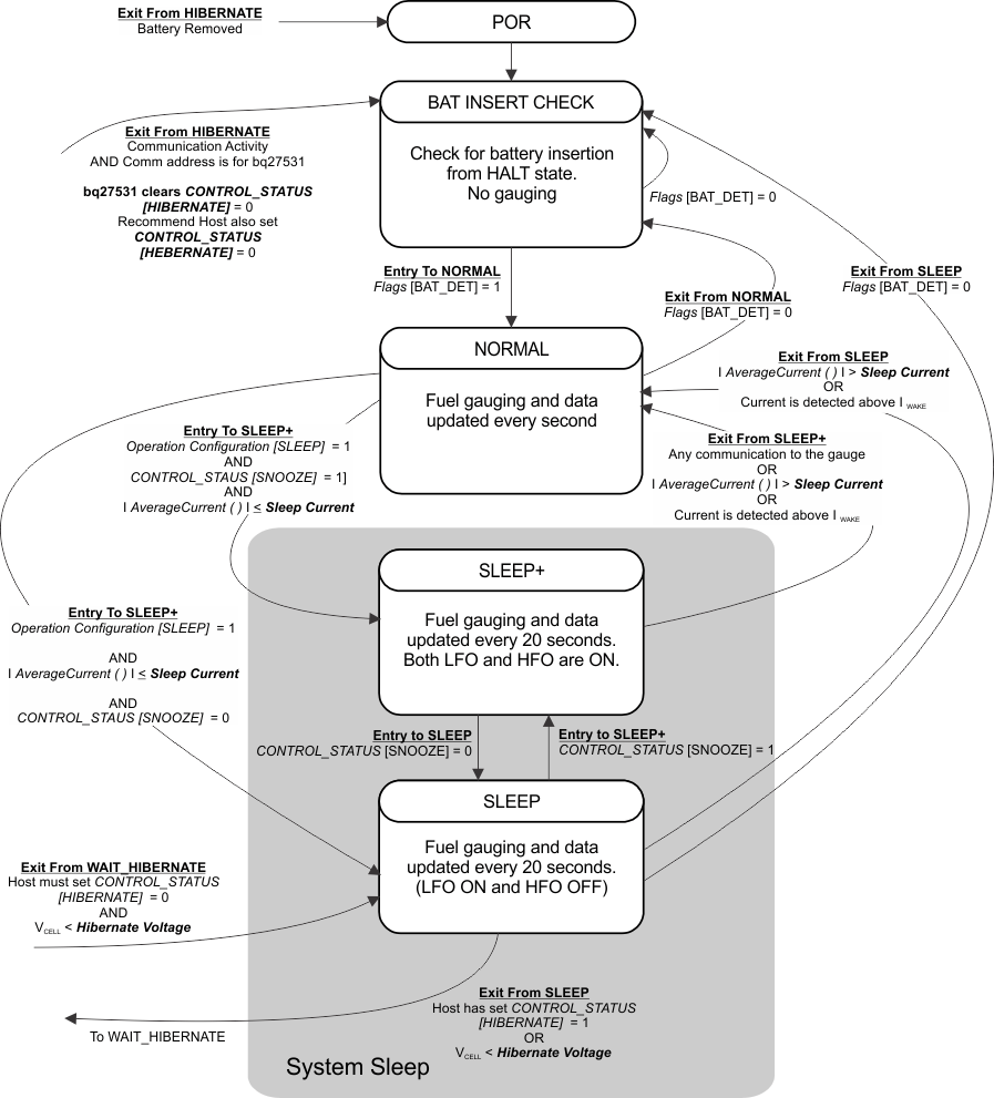
8.4.1.3 SLEEP Mode
SLEEP mode is entered automatically if the feature is enabled (Op Config [SLEEP] = 1) and AverageCurrent() is below the programmable level Sleep Current. Once entry into SLEEP mode has been qualified, but prior to entering it, the fuel gauge performs a coulomb counter autocalibration to minimize offset.
During SLEEP mode, the fuel gauge periodically takes data measurements and updates its data set. However, a majority of its time is spent in an idle condition.
The fuel gauge exits SLEEP mode if any entry condition is broken, specifically when:
- AverageCurrent() rises above Sleep Current, or
- A current in excess of IWAKE through RSENSE is detected.
In the event that a battery is removed from the system while a charger is present (and powering the gauge), Impedance Track updates are not necessary. Hence, the fuel gauge enters a state that checks for battery insertion and does not continue executing the Impedance Track algorithm.
 Figure 8-1 Power Mode Diagram—System Sleep
 Figure 8-2 Power Mode Diagram—System Shutdown