SLVSDN2E January 2018 – March 2021 DRV10974
PRODUCTION DATA
- 1 Features
- 2 Applications
- 3 Description
- 4 Revision History
- 5 Pin Configuration and Functions
- 6 Specifications
-
7 Detailed Description
- 7.1 Overview
- 7.2 Functional Block Diagram
- 7.3 Feature Description
- 7.4 Device Functional Modes
- 8 Application and Implementation
- 9 Power Supply Recommendations
- 10Layout
- 11Device and Documentation Support
- 12Mechanical, Packaging, and Orderable Information
Package Options
Mechanical Data (Package|Pins)
Thermal pad, mechanical data (Package|Pins)
Orderable Information
7.4.5 Control Advance Angle
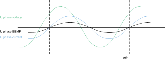
To achieve the best efficiency, the drive state of the motor must be controlled such that the current is aligned with the BEMF voltage of the motor. Figure 7-15 illustrates the operation when the drive angle has been optimized. For complete flexibility, the DRV10974 device offers a wide range of fixed lead times. The options for lead time are controlled by a resistor on the ADV pin. The values available are shown in Table 7-4.
 Figure 7-15 Drive Angle Adjustment
Table 7-4 Lead Time Selection
| RADV [kΩ](1) | LEAD TIME [µs] |
|---|---|
| 10.7 | 10 |
| 14.3 | 25 |
| 17.8 | 50 |
| 22.1 | 100 |
| 28 | 150 |
| 34 | 200 |
| 41.2 | 250 |
| 49.9 | 300 |
| 59 | 400 |
| 71.5 | 500 |
| 86.6 | 600 |
| 105 | 700 |
| 124 | 800 |
| 150 | 900 |
| 182 | 1000 |
(1) All resistors are ±1%.