SBOS547A June 2011 – August 2015 INA226
PRODUCTION DATA.
- 1 Features
- 2 Applications
- 3 Description
- 4 Revision History
- 5 Pin Configuration and Functions
- 6 Specifications
-
7 Detailed Description
- 7.1 Overview
- 7.2 Functional Block Diagram
- 7.3 Feature Description
- 7.4 Device Functional Modes
- 7.5 Programming
- 7.6
Register Maps
- 7.6.1 Configuration Register (00h) (Read/Write)
- 7.6.2 Shunt Voltage Register (01h) (Read-Only)
- 7.6.3 Bus Voltage Register (02h) (Read-Only)
- 7.6.4 Power Register (03h) (Read-Only)
- 7.6.5 Current Register (04h) (Read-Only)
- 7.6.6 Calibration Register (05h) (Read/Write)
- 7.6.7 Mask/Enable Register (06h) (Read/Write)
- 7.6.8 Alert Limit Register (07h) (Read/Write)
- 7.6.9 Manufacturer ID Register (FEh) (Read-Only)
- 7.6.10 Die ID Register (FFh) (Read-Only)
- 8 Application and Implementation
- 9 Power Supply Recommendations
- 10Layout
- 11Device and Documentation Support
- 12Mechanical, Packaging, and Orderable Information
Package Options
Mechanical Data (Package|Pins)
- DGS|10
Thermal pad, mechanical data (Package|Pins)
Orderable Information
8 Application and Implementation
NOTE
Information in the following applications sections is not part of the TI component specification, and TI does not warrant its accuracy or completeness. TI’s customers are responsible for determining suitability of components for their purposes. Validate and test the design implementation to confirm system functionality.
8.1 Application Information
The INA226 is a current shunt and power monitor with an I2C™ compatible interface. The device monitors both a shunt voltage drop and bus supply voltage. Programmable calibration value, conversion times, and averaging, combined with an internal multiplier, enable direct readouts of current in amperes and power in watts.
8.2 Typical Applications
8.2.1 High-Side Sensing Circuit Application
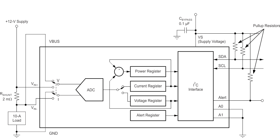
 Figure 27. Typical Circuit Configuration, INA226
8.2.1.1 Design Requirements
INA226 measures the voltage developed across a current-sensing resistor (RSHUNT) when current passes through it. The device also measures the bus supply voltage and can calculate power when calibrated. It comes with alert capability where the alert pin can be programmed to respond to a user-defined event or to a conversion ready notification. This design illustrates the ability of the alert pin to respond to a set threshold.
8.2.1.2 Detailed Design Procedure
The Alert pin can be configured to respond to one of the five alert functions described in the Alert Pin section. The alert pin must to be pulled up to the VVS pin voltage via the pull-up resistors. The configuration register is set based on the required conversion time and averaging. The Mask/Enable Register is set to identify the required alert function and the Alert Limit Register is set to the limit value used for comparison.
8.2.1.3 Application Curves
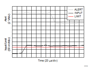
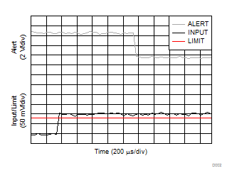
Figure 28 shows the Alert pin response to a shunt voltage over-limit of 80 mV for a conversion time (tCT) of 1.1 ms and averaging set to 1. Figure 29 shows the response for the same limit but with the conversion time reduced to 140 µs.
Table 19. Configuration Register (00h) Settings for Figure 28 (Value = 4025h)
| BIT # | D15 | D14 | D13 | D12 | D11 | D10 | D9 | D8 | D7 | D6 | D5 | D4 | D3 | D2 | D1 | D0 |
|---|---|---|---|---|---|---|---|---|---|---|---|---|---|---|---|---|
| BIT NAME |
RST | — | — | — | AVG2 | AVG1 | AVG0 | VBUSCT2 | VBUSCT1 | VBUSCT0 | VSHCT2 | VSHCT1 | VSHCT0 | MODE3 | MODE2 | MODE1 |
| POR VALUE | 0 | 1 | 0 | 0 | 0 | 0 | 0 | 0 | 0 | 0 | 1 | 0 | 0 | 1 | 0 | 1 |
Table 20. Configuration Register (00h) Settings for Figure 29 (Value = 4005h)
| BIT # | D15 | D14 | D13 | D12 | D11 | D10 | D9 | D8 | D7 | D6 | D5 | D4 | D3 | D2 | D1 | D0 |
|---|---|---|---|---|---|---|---|---|---|---|---|---|---|---|---|---|
| BIT NAME |
RST | — | — | — | AVG2 | AVG1 | AVG0 | VBUSCT2 | VBUSCT1 | VBUSCT0 | VSHCT2 | VSHCT1 | VSHCT0 | MODE3 | MODE2 | MODE1 |
| POR VALUE | 0 | 1 | 0 | 0 | 0 | 0 | 0 | 0 | 0 | 0 | 0 | 0 | 0 | 1 | 0 | 1 |

