SNVSC12 April 2021 LM117QML-SP
PRODUCTION DATA
- 1 Features
- 2 Applications
- 3 Description
- 4 Revision History
- 5 Device Comparison Table
- 6 Pin Configurations and Functions
-
7 Specifications
- 7.1 Absolute Maximum Ratings
- 7.2 ESD Ratings
- 7.3 Recommended Operating Conditions
- 7.4 Thermal Information
- 7.5 Electrical Characteristics: 0.5–A IOUT Devices (LM117H, LM117GW)
- 7.6 Parameter Drift: 0.5–A IOUT Devices (LM117H, LM117GW)
- 7.7 Electrical Characteristics: 1.5–A IOUT Devices (LM117K)
- 7.8 Parameter Drift: 1.5–A IOUT Devices (LM117K)
- 7.9 Quality Conformance Inspection
- 7.10 Typical Characteristics
- 8 Detailed Description
- 9 Application and Implementation
- 10Power Supply Recommendations
- 11Layout
- 12Device and Documentation Support
Package Options
Refer to the PDF data sheet for device specific package drawings
Mechanical Data (Package|Pins)
- K|2
- NAC|16
- Y|0
- NDT|3
Thermal pad, mechanical data (Package|Pins)
Orderable Information
8.6 Protection Diodes
When external capacitors are used with an IC regulator, it is sometimes necessary to add protection diodes to prevent the capacitors from discharging through low current points into the regulator. Most 10-μF capacitors have low enough internal series resistance to deliver 20-A spikes when shorted. Although the surge is short, there is enough energy to damage parts of the IC.
When an output capacitor is connected to a regulator and the input is shorted, the output capacitor will discharge into the output of the regulator. The discharge current depends on the value of the capacitor, the output voltage of the regulator, and the rate of decrease of VIN. In the LM117, this discharge path is through a large junction that is able to sustain 15-A surge. This is not true of all types of positive regulators. For output capacitors of 25 μF or less, there is generally no need to use diodes.
The bypass capacitor on the adjustment terminal can discharge through a low current junction. Discharge occurs when either the input or output is shorted. Internal to the LM117 is a 50-Ω resistor which limits the peak discharge current. No protection is needed for output voltages of 25 V or less and 10-μF capacitance. Figure 8-4 shows an LM117 with protection diodes included for use with outputs greater than 25 V and high values of output capacitance.
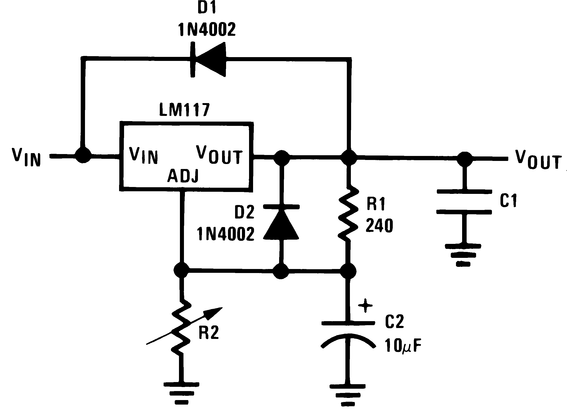

D2 protects against C2 (such as due to a VOUT short)