SNVS678F June 2010 – November 2015 LM3414 , LM3414HV
PRODUCTION DATA.
- 1 Features
- 2 Applications
- 3 Description
- 4 Revision History
- 5 Pin Configuration and Functions
- 6 Specifications
- 7 Detailed Description
- 8 Application and Implementation
- 9 Power Supply Recommendations
- 10Layout
- 11Device and Documentation Support
- 12Mechanical, Packaging, and Orderable Information
Package Options
Mechanical Data (Package|Pins)
Thermal pad, mechanical data (Package|Pins)
- DDA|8
Orderable Information
1 Features
- Supports LED Power up to 60 W (1): 18x 3-W HBLEDs
- Requires No External Current Sensing Resistor
- ±3% LED Current Accuracy
- Up to 96% Efficiency
- High Contrast Ratio (Minimum Dimming Current Pulse Width <10 µS)
- Integrated Low-Side N-Channel MOSFET
- Adjustable Constant LED Current From 350 mA to 1000 mA
- Support Analog Dimming and Thermal Fold-Back
- Wide Input Voltage Range:
- 4.5 V to 42 V (LM3414)
- 4.5 V to 65 V (LM3414HV)
- Constant Switching Frequency Adjustable from 250 kHz to 1000 kHz
- Thermal Shutdown Protection
- Power Enhanced SOIC-8 or 3 mm × 3 mm WSON-8 Package
2 Applications
- High Power LED Drivers
- Architectural Lighting, Office Troffers
- Automotive Lighting
- MR-16 LED Lamps
3 Description
The LM3414 and LM3414HV are 1-A 60-W(1) common anode-capable constant current buck LED drivers. They are suitable for driving single string of 3-W HBLED with up to 96% efficiency. They accept input voltages from 4.5 VDC to 65 VDC and deliver up to 1-A average LED current with ±3% accuracy. The integrated low-side N-channel power MOSFET and current sensing element realize simple and low component count circuitry, as no bootstrapping capacitor and external current-sensing resistor are required. An external small-signal resistor to ground provides very fine LED current adjustment, analog dimming, and thermal fold-back functions.
Constant switching frequency operation eases EMI. No external loop compensation network is needed. The proprietary Pulse-Level-Modulation (PLM) control method benefits in high conversion efficiency and true average LED current regulation. Fast response time realizes fine LED current pulse fulfilling the 240 Hz 256-step dimming resolution requirement for general lighting.
The LM3414 and LM3414HV are available in SOIC-8 and 3 mm × 3 mm WSON-8 packages.
Device Information(2)
| PART NUMBER | PACKAGE | BODY SIZE (NOM) |
|---|---|---|
| LM3414, LM3414HV |
WSON (8) | 3.00 mm × 3.00 mm |
| SOIC (8) | 3.90 mm × 4.89 mm |
- Thermal derating applies according to actual operation conditions.
- For all available packages, see the orderable addendum at the end of the data sheet.
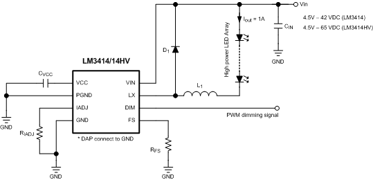
Simplified Application Schematic
