SLOS456N January 2005 – October 2017
PRODUCTION DATA.
- 1 Features
- 2 Applications
- 3 Description
- 4 Revision History
- 5 Pin Configuration and Functions
-
6 Specifications
- 6.1 Absolute Maximum Ratings
- 6.2 ESD Ratings
- 6.3 Recommended Operating Conditions
- 6.4 Thermal Information
- 6.5 LM4040A20I, LM4040B20I Electrical Characteristics
- 6.6 LM4040C20I, LM4040D20I Electrical Characteristics
- 6.7 LM4040C20Q, LM4040D20Q Electrical Characteristics
- 6.8 LM4040A25I, LM4040B25I Electrical Characteristics
- 6.9 LM4040C25I, LM4040D25I Electrical Characteristics
- 6.10 LM4040C25Q, LM4040D25Q Electrical Characteristics
- 6.11 LM4040A30I, LM4040B30I Electrical Characteristics
- 6.12 LM4040C30I, LM4040D30I Electrical Characteristics
- 6.13 LM4040C30Q, LM4040D30Q Electrical Characteristics
- 6.14 LM4040A41I, LM4040B41I Electrical Characteristics
- 6.15 LM4040C41I, LM4040D41I Electrical Characteristics
- 6.16 LM4040A50I, LM4040B50I Electrical Characteristics
- 6.17 LM4040C50I, LM4040D50I Electrical Characteristics
- 6.18 LM4040C50Q, LM4040D50Q Electrical Characteristics
- 6.19 LM4040A82I, LM4040B82I Electrical Characteristics
- 6.20 LM4040C82I, LM4040D82I Electrical Characteristics
- 6.21 LM4040A10I, LM4040B10I Electrical Characteristics
- 6.22 LM4040C10I, LM4040D10I Electrical Characteristics
- 6.23 Typical Characteristics
- 7 Detailed Description
- 8 Applications and Implementation
- 9 Power Supply Recommendations
- 10Layout
- 11Device and Documentation Support
- 12Mechanical, Packaging, and Orderable Information
Package Options
Mechanical Data (Package|Pins)
Thermal pad, mechanical data (Package|Pins)
Orderable Information
7 Detailed Description
7.1 Overview
The LM4040 is a precision micro-power curvature-corrected bandgap shunt voltage reference. The LM4040 has been designed for stable operation without the need of an external capacitor connected between the “+” pin and the “−” pin. If, however, a bypass capacitor is used, the LM4040 remains stable.
LM4040 offers several fixed reverse breakdown voltages: 2.048 V, 2.500 V, 3.000 V, 4.096 V, 5.000 V, 6.000, 8.192 V, and 10.000 V. The minimum operating current increases from 60 µA for the LM4040-N-2.048 and LM4040-N-2.5 to 100 μA for the 10.0-V LM4040. All versions have a maximum operating current of 15 mA.
Each reverse voltage options can be purchased with initial tolerances (at 25°C) of 0.1%, 0.2%, 0.5% and 1.0%. These reference options are denoted by A (0.1%), B (0.2%), C (0.5%) and D for (1.0%).
The LM4040xxxI devices are characterized for operation from –40°C to 85°C, and the LM4040xxxQ devices are characterized for operation from –40°C to 125°C.
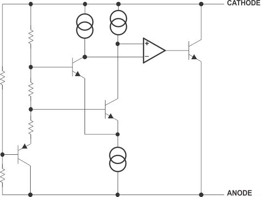
7.2 Functional Block Diagram

7.3 Feature Description
A temperature compensated band gap voltage reference controls high gain amplifier and shunt pass element to maintain a nearly constant voltage between cathode and anode. Regulation occurs after a minimum current is provided to power the voltage divider and amplifier. Internal frequency compensation provides a stable loop for all capacitor loads. Floating shunt design is useful for both positive and negative regulation applications.
7.4 Device Functional Modes
7.4.1 Shunt Reference
LM4040 will operate in one mode, which is as a fixed voltage reference that cannot be adjusted. LM4040 does offer various Reverse Voltage options that have unique electrical characteristics detailed in the Specifications section.
In order for a proper Reverse Voltage to be developed, current must be sourced into the cathode of LM4040. The minimum current needed for proper regulation is denoted in the Specifications section as IZ,min.