SNOSB29H November 2009 – May 2022 LMP8645 , LMP8645HV
PRODUCTION DATA
- 1 Features
- 2 Applications
- 3 Description
- 4 Revision History
- 5 Pin Configuration and Functions
- 6 Specifications
- 7 Detailed Description
- 8 Application and Implementation
- 9 Power Supply Recommendations
- 10Layout
- 11Device and Documentation Support
- 12Mechanical, Packaging, and Orderable Information
Package Options
Mechanical Data (Package|Pins)
- DDC|6
Thermal pad, mechanical data (Package|Pins)
Orderable Information
8.2.2 High Brightness LED Driver
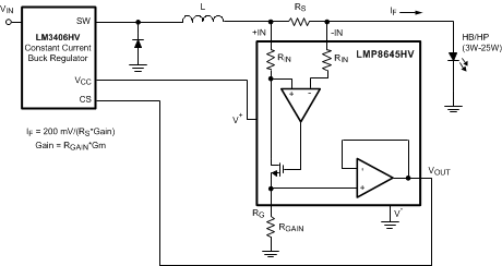
The LMP8645 is the right choice in applications which require high-side current sense, such as High Brightness LED for automotive where the cathode of the LED must be connected to the ground (chassis) of the car. In Figure 8-4, the LMP8645 is used to monitor the current High Side in a high brightness LED together with a LM3406 constant current buck regulator LED driver.
 Figure 8-4 High-Side Current Sensing in Driving HP/HB LED
Even though LMP8645 will work in all 3 Ranges, RGAIN will be calculated according to Range 3 because the purpose is regulating the current in the LEDs when the external MOSFET is OFF (LMP8645 at high VCM). Even if this approach makes the LMP8645 able to sense high peak current only in Range 3 where the dynamic output is higher than Range 1 the current resolution is maximized. At each switch ON/OFF of the MOSFET the LMP8645 goes from Range 1 (MOSFET ON, string of LED OFF), to Range 3 (MOSFET OFF, string of LED ON) passing through Range 2 (MOSFET OFF, string of LED OFF). Because the purpose of the application is to sense the current with high precision when the LED string is ON, the RGAIN will be calculated according to the Range 3.
The LMP8645 supply voltage is supplied by the internal LDO of the LM3406 thorough the pin VCC. The LM340x is expecting a 200-mV feedback signal at the current sense (SNS) pin. The LMP8645 must provide this 200 mV at the determined current limit.
The current which flows through the LED is programmed according to Equation 8:
where:
- Gain = RGAIN × Gm
- VCS = 200 mV
In this application the current which flows in the HB LED is in the Range from 350 mA to 1 A, so to reduce the power dissipation on the shunt resistor and have a good accuracy, the RS must be in the range from 50 mΩ and 200 mΩ. In Table 8-1, two examples are analyzed.
To summarize, calculate the RGAIN according to the range of operation in which the application mainly works. Once selected, the range considers the more stringent constraint
| IF=350 mA | IF=1 A | |
|---|---|---|
| RGAIN | 40 kΩ | 36 kΩ |
| RS | 77 mΩ | 27 mΩ |
| Dissipated Power | 9.5 mW | 27 mW |
| Total Accuracy | ≊5% | ≊5% |