SNAS506I January 2011 – December 2014 LMP91000
PRODUCTION DATA.
- 1 Features
- 2 Applications
- 3 Description
- 4 Revision History
- 5 Pin Configuration and Functions
- 6 Specifications
-
7 Detailed Description
- 7.1 Overview
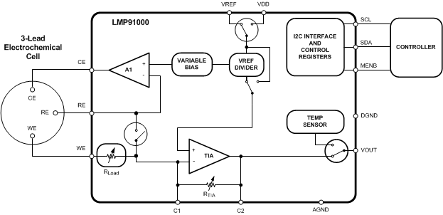
- 7.2 Functional Block Diagram
- 7.3 Feature Description
- 7.4 Device Functional Modes
- 7.5 Programming
- 7.6 Registers Maps
- 8 Application and Implementation
- 9 Power Supply Recommendations
- 10Layout
- 11Device and Documentation Support
- 12Mechanical, Packaging, and Orderable Information
Package Options
Mechanical Data (Package|Pins)
- NHL|14
Thermal pad, mechanical data (Package|Pins)
Orderable Information
1 Features
- Typical Values, TA = 25°C
- Supply Voltage 2.7 V to 5.25 V
- Supply Current (Average Over Time) <10 µA
- Cell Conditioning Current Up to 10 mA
- Reference Electrode Bias Current (85°C) 900pA (max)
- Output Drive Current 750 µA
- Complete Potentiostat Circuit-to-Interface to Most Chemical Cells
- Programmable Cell Bias Voltage
- Low-Bias Voltage Drift
- Programmable TIA gain 2.75 kΩ to 350 kΩ
- Sink and Source Capability
- I2C Compatible Digital Interface
- Ambient Operating Temperature –40°C to 85°C
- Package 14-Pin WSON
- Supported by WEBENCH® Sensor AFE Designer
2 Applications
- Chemical Species Identification
- Amperometric Applications
- Electrochemical Blood Glucose Meter
3 Description
The LMP91000 is a programmable analog front-end (AFE) for use in micro-power electrochemical sensing applications. It provides a complete signal path solution between a sensor and a microcontroller that generates an output voltage proportional to the cell current. The LMP91000’s programmability enables it to support multiple electrochemical sensors such as 3-lead toxic gas sensors and 2-lead galvanic cell sensors with a single design as opposed to the multiple discrete solutions. The LMP91000 supports gas sensitivities over a range of 0.5 nA/ppm to 9500 nA/ppm. It also allows for an easy conversion of current ranges from 5 µA to 750 µA full scale.
The LMP91000’s adjustable cell bias and transimpedance amplifier (TIA) gain are programmable through the I2C interface. The I2C interface can also be used for sensor diagnostics. An integrated temperature sensor can be read by the user through the VOUT pin and used to provide additional signal correction in the µC or monitored to verify temperature conditions at the sensor.
The LMP91000 is optimized for micro-power applications and operates over a voltage range of 2.7 to 5.25 V. The total current consumption can be less than 10 μA. Further power savings are possible by switching off the TIA amplifier and shorting the reference electrode to the working electrode with an internal switch.
Device Information(1)
| PART NUMBER | PACKAGE | BODY SIZE (NOM) |
|---|---|---|
| LMP91000 | WSON (14) | 4.00 mm × 4.00 mm |
- For all available packages, see the orderable addendum at the end of the datasheet.
Simplified Application Schematic