SBOS724A September 2015 – June 2022 OPA1688
PRODUCTION DATA
- 1 Features
- 2 Applications
- 3 Description
- 4 Revision History
- 5 Device Comparison Table
- 6 Pin Configuration and Functions
- 7 Specifications
- 8 Detailed Description
- 9 Applications and Implementation
- 10Power Supply Recommendations
- 11Layout
- 12Device and Documentation Support
- 13Mechanical, Packaging, and Orderable Information
Package Options
Mechanical Data (Package|Pins)
Thermal pad, mechanical data (Package|Pins)
- DRG|8
Orderable Information
9.2.1.3 Application Curves
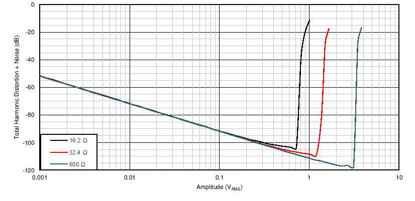
The headphone amplifier circuit in Figure 9-1 is tested with three common headphone impedances: 16 Ω, 32 Ω, and 600 Ω. The total harmonic distortion and noise (THD+N) for increasing output voltages is given in Figure 9-3. This measurement is performed with a 1-kHz input signal and a measurement bandwidth of 22.4 kHz. The maximum output power and THD+N before clipping are given in Table 9-1. The maximum output power into low-impedance headphones is limited by the output current capabilities of the amplifier. For high-impedance headphones (600 Ω), the output voltage capabilities of the amplifier are the limiting factor. The circuit in Figure 9-1 is tested using ±5-V supplies that are common in many portable systems. However, using higher supply voltages increases the output power into 600-Ω headphones.

| Input signal = 1 kHz, measurement bandwidth = 22.4 kHz |
| LOAD IMPEDANCE (Ω) | MAXIMUM OUTPUT POWER BEFORE CLIPPING (mW) | THD+N AT MAXIMUM OUTPUT POWER (dB) |
|---|---|---|
| 16 | 32 | –104.1 |
| 32 | 50 | –109.5 |
| 600 | 16 | –117.8 |
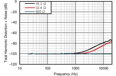
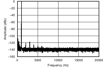
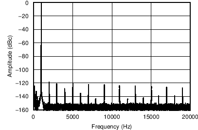
Figure 9-4, Figure 9-5, and Figure 9-6 further illustrate the exceptional performance of the OPA1688 as a headphone amplifier.
Figure 9-4 shows the THD+N over frequency for a 500-mVRMS output signal into the same three load impedances previously tested.

| 90-kHz measurement bandwidth |
Figure 9-5 and Figure 9-6 show the output spectrum of the OPA1688 at low (1 mW) and high (50 mW) output power levels into a 32-Ω load. The distortion harmonics in both cases are approximately 120 dB below the fundamental.

| Third harmonic is dominant at a level of –117.6 dB relative to the fundamental |

| Highest harmonic is the second harmonic at –119 dB below the fundamental |