SBVS020C September 2000 – February 2020 REF200
PRODUCTION DATA.
- 1 Features
- 2 Applications
- 3 Description
- 4 Revision History
- 5 Pin Configuration and Functions
- 6 Specifications
- 7 Detailed Description
- 8 Application and Implementation
- 9 Power Supply Recommendations
- 10Layout
- 11Device and Documentation Support
- 12Mechanical, Packaging, and Orderable Information
Package Options
Mechanical Data (Package|Pins)
- D|8
Thermal pad, mechanical data (Package|Pins)
Orderable Information
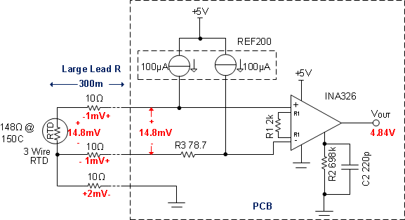
8.2.2.1 Lead Resistance Cancelation (3-Wire RTD)
Figure 14 shows the 3-wire RTD configuration can be used to cancel lead resistance. The resistance in each lead must be equal to cancel the error. Also, the two current sources in the REF200 must be equal. Notice that the voltage developed on the two top leads of the RTD are equal and opposite polarity so that the amplifiers input is only from the RTD voltage. In this example, the RTD drop is 14.8 mV and the leads each have 1 mV. Notice that the 1 mV drops cancel. Finally, notice that the voltage on the 3rd lead (2 mV) creates a small shift in the common mode voltage. In some applications, a larger resistor is intentionally added to shift the common-mode voltage. However, the INA326 has a rail-to-rail common mode range, so it can accept common-mode voltages near ground.
 Figure 14. 3-Wire RTD Configuration Cancels Lead Resistance