SCLS078H December 1982 – April 2021 SN54HC04 , SN74HC04
PRODUCTION DATA
- 1 Features
- 2 Applications
- 3 Description
- 4 Revision History
- 5 Pin Configuration and Functions
-
6 Specifications
- 6.1 Absolute Maximum Ratings
- 6.2 ESD Ratings
- 6.3 Recommended Operating Conditions
- 6.4 Thermal Information
- 6.5 Electrical Characteristics - 74
- 6.6 Electrical Characteristics - 54
- 6.7 Switching Characteristics - 74
- 6.8 Switching Characteristics - 54
- 6.9 Operating Characteristics
- 6.10 Typical Characteristics
- 7 Parameter Measurement Information
- 8 Detailed Description
- 9 Application and Implementation
- 10Power Supply Recommendations
- 11Layout
- 12Device and Documentation Support
- 13Mechanical, Packaging, and Orderable Information
Package Options
Refer to the PDF data sheet for device specific package drawings
Mechanical Data (Package|Pins)
- D|14
- DB|14
- PW|14
- N|14
- NS|14
Thermal pad, mechanical data (Package|Pins)
- PW|14
Orderable Information
3 Description
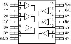
This device contains six independent inverters. Each gate performs the Boolean function Y = A in positive logic.
Device Information(1)
| PART NUMBER | PACKAGE | BODY SIZE (NOM) |
|---|---|---|
| SN74HC04D | SOIC (14) | 8.70 mm × 3.90 mm |
| SN74HC04DB | SSOP (14) | 6.50 mm × 5.30 mm |
| SN74HC04N | PDIP (14) | 19.30 mm × 6.40 mm |
| SN74HC04NS | SO (14) | 10.20 mm × 5.30 mm |
| SN74HC04PW | TSSOP (14) | 5.00 mm × 4.40 mm |
| SN54HC04J | CDIP (14) | 21.30 mm × 7.60 mm |
| SN54HC04W | CFP (14) | 9.20 mm × 6.29 mm |
| SN54HC04FK | LCCC (20) | 8.90 mm × 8.90 mm |
(1) For all available packages, see the orderable addendum at the
end of the data sheet.
 Functional pinout