SBOS891C October 2018 – September 2023 TMP144
PRODUCTION DATA
- 1
- 1 Features
- 2 Applications
- 3 Description
- 4 Revision History
- 5 Pin Configuration and Functions
- 6 Specifications
- 7 Detailed Description
- 8 Application and Implementation
- 9 Device and Documentation Support
- 10Mechanical, Packaging, and Orderable Information
Package Options
Refer to the PDF data sheet for device specific package drawings
Mechanical Data (Package|Pins)
- YBK|4
- YFF|4
- YMT|4
Thermal pad, mechanical data (Package|Pins)
Orderable Information
7.5.3 Global Initialization and Address Assignment Sequence
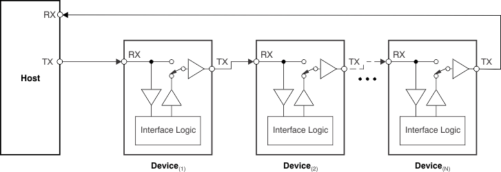
At device power-up, every TMP144 in the daisy-chain is connected in transparent mode, as shown in Figure 7-7.
 Figure 7-7 TMP144 Daisy-Chain: Bus Status at Start of Global Initialization
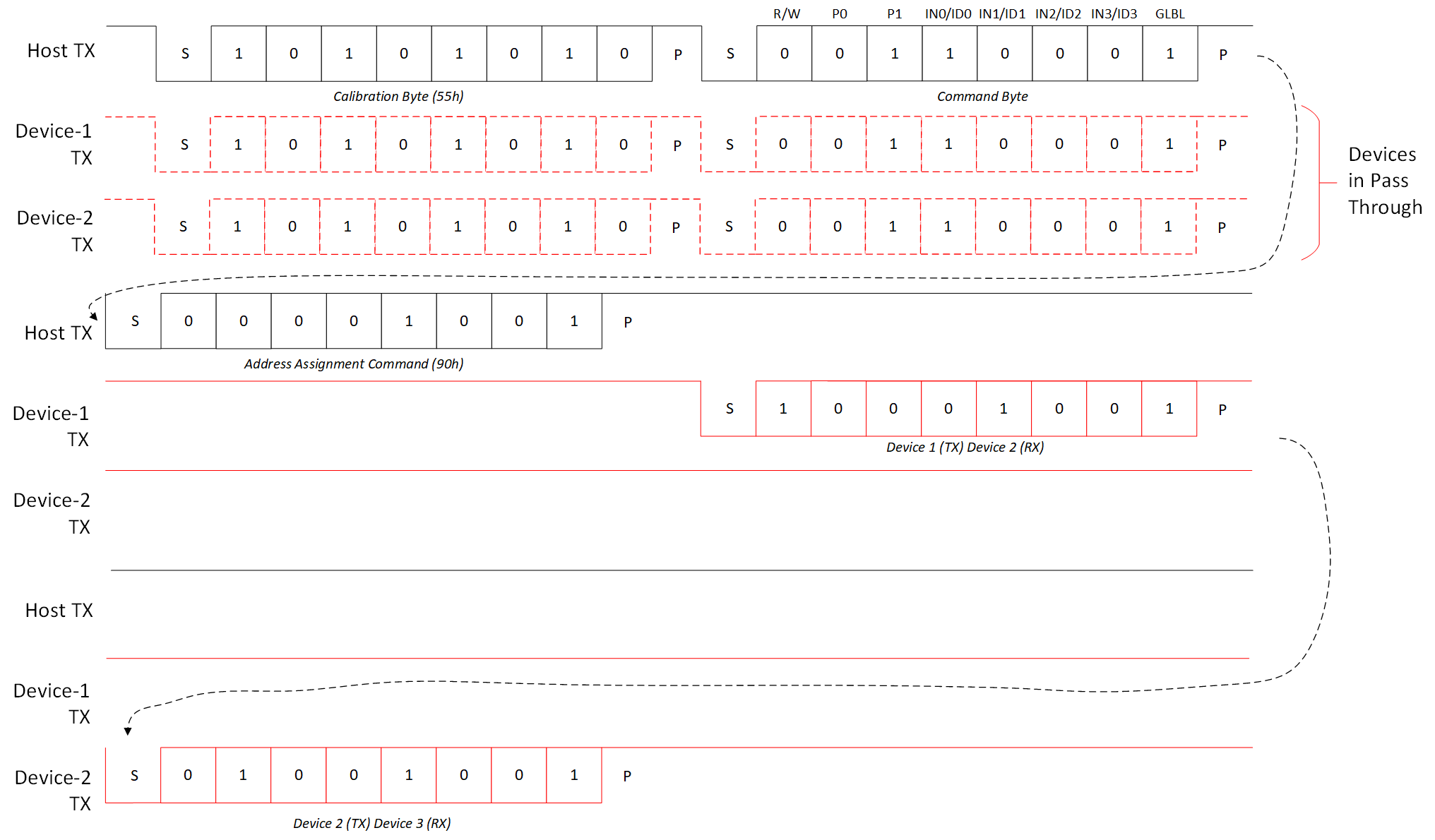
As shown in Figure 7-8, the host must send the initialization command (C[7:0] = 10001100) for the bus to program its internal address, depending on the number of devices on the bus.
 Figure 7-8 Global Initialization and
Address Assignment Command Flow.
  Figure 7-9 TMP144
Daisy-Chain: Bus Status at Start of Address Assignment
Figure 7-9 TMP144
Daisy-Chain: Bus Status at Start of Address AssignmentThe host must then send the address assignment command, consisting of C[7:4] = 1001 and C[3:0] = 0000, where C[3:0] represents the address of the first device in the chain. This word is stored internally as its device ID. The first device increments the unit in the device address and then reconnects the bus, as shown in Figure 7-10. This address is then sent to the next device in the chain.
 Figure 7-10 TMP144
Daisy-Chain: Bus Status After First Device Address Assignment
Figure 7-10 TMP144
Daisy-Chain: Bus Status After First Device Address AssignmentAfter all devices on the chain have received the respective addresses, the host receives the last programmed address on the chain + 1. The host can use this information to determine the total number of devices in the chain and the respective address of each device.
After the initialization sequence, every device can be addressed individually or through global commands. This global initialization sequence is a requirement and must be performed before any other communication.