SBOS383D December 2006 – December 2016 TMP411
PRODUCTION DATA.
- 1 Features
- 2 Applications
- 3 Description
- 4 Revision History
- 5 Device Comparison Table
- 6 Pin Configuration and Functions
- 7 Specifications
- 8 Typical Characteristics
-
9 Detailed Description
- 9.1 Overview
- 9.2 Functional Block Diagram
- 9.3 Feature Description
- 9.4 Device Functional Modes
- 9.5 Programming
- 9.6
Register Map
- 9.6.1 Register Information
- 9.6.2 Pointer Register
- 9.6.3 Temperature Registers
- 9.6.4 Limit Registers
- 9.6.5 Status Register
- 9.6.6 Configuration Register
- 9.6.7 Resolution Register
- 9.6.8 Conversion Rate Register
- 9.6.9 N-Factor Correction Register
- 9.6.10 Minimum and Maximum Registers
- 9.6.11 Consecutive Alert Register
- 9.6.12 THERM Hysteresis Register
- 9.6.13 Remote Temperature Offset Register
- 9.6.14 Identification Registers
- 10Application and Implementation
- 11Power Supply Recommendations
- 12Layout
- 13Device and Documentation Support
- 14Mechanical, Packaging, and Orderable Information
Package Options
Mechanical Data (Package|Pins)
Thermal pad, mechanical data (Package|Pins)
- DGK|8
Orderable Information
1 Features
- ±1°C Remote Diode Sensor
- ±1°C Local Temperature Sensor
- Programmable Non-Ideality Factor
- Series Resistance Cancellation
- Alert Function
- Offset Registers for System Calibration
- Pin and Registers Compatible With ADT7461 and ADM1032
- Programmable Resolution: 9 to 12 Bits
- Programmable Threshold Limits
- Two-Wire and SMBus Serial Interface
- Minimum and Maximum Temperature Monitors
- Multiple Interface Addresses
- ALERT and THERM2 Pin Configuration
- Diode Fault Detection
2 Applications
- LCD and DLP and LCOS Projectors
- Servers
- Industrial Controllers
- Central Office Telecom Equipment
- Desktop and Notebook Computers
- Storage Area Networks (SAN)
- Industrial and Medical Equipment
- Processor and FPGA Temperature Monitoring
3 Description
The TMP411 device is a remote temperature sensor monitor with a built-in local temperature sensor. The remote temperature-sensor, diode-connected transistors are typically low-cost, NPN- or PNP-type transistors or diodes that are an integral part of microcontrollers, microprocessors, or FPGAs.
Remote accuracy is ±1°C for multiple device manufacturers, with no calibration needed. The two-wire serial interface accepts SMBus write byte, read byte, send byte and receive byte commands to program the alarm thresholds and to read temperature data.
Features that are included in the TMP411 device are: series resistance cancellation, programmable non-ideality factor, programmable resolution, programmable threshold limits, user-defined offset register for maximum accuracy, minimum and maximum temperature monitors, wide remote temperature measurement range (up to 150°C), diode fault detection, and temperature alert function.
The TMP411 device is available in VSSOP-8 and SOIC-8 packages.
Device Information(1)
| PART NUMBER | PACKAGE | BODY SIZE (NOM) |
|---|---|---|
| TMP411 | VSSOP (8) | 3.00 mm × 3.00 mm |
| SOIC (8) | 4.90 mm × 3.91 mm |
- For all available packages, see the orderable addendum at the end of the data sheet.
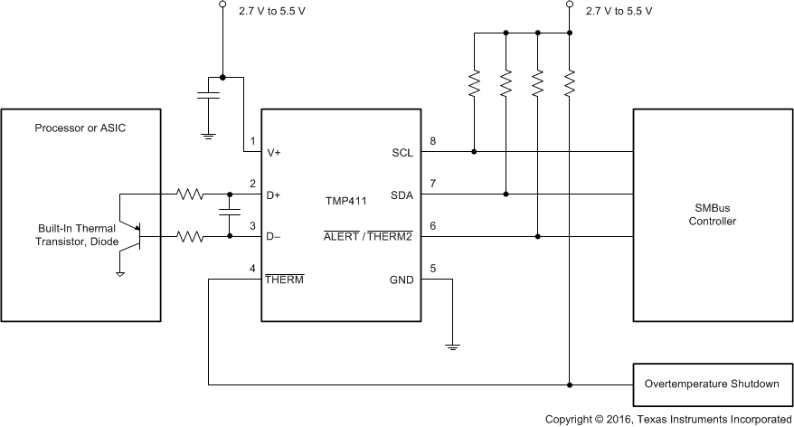
Simplified Block Diagram
