SNIS210G April 2019 – November 2023 TMP61-Q1
PRODUCTION DATA
- 1
- 1 Features
- 2 Applications
- 3 Description
- 4 Device Comparison
- 5 Pin Configuration and Functions
- 6 Specifications
- 7 Detailed Description
- 8 Application and Implementation
- 9 Device and Documentation Support
- 10Revision History
- 11Mechanical, Packaging, and Orderable Information
Package Options
Mechanical Data (Package|Pins)
Thermal pad, mechanical data (Package|Pins)
Orderable Information
8.3.1.2.1 Thermal Protection With Comparator
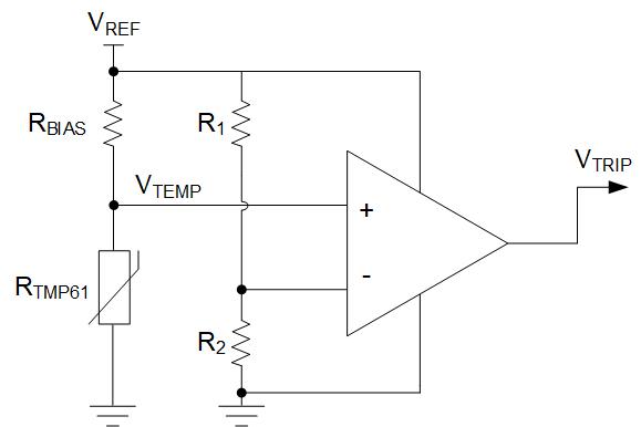
Use the TMP61-Q1 device along with a voltage reference, and a comparator to program the thermal protection. As shown in Figure 8-10, the output of the comparator remains low until the voltage of the thermistor divider, with RBIAS and RTMP61, rises above the threshold voltage set by R1 and R2. When the output goes high, the comparator signals an overtemperature warning signal. The engineer can also program the hysteresis to prevent the output from continuously toggling around the temperature threshold when the output returns low. Either a comparator with built-in hysteresis or feedback resistors may be used.
 Figure 8-10 Temperature Switch Using TMP61-Q1 Voltage Divider and a Comparator