SBOSA22A December 2021 – August 2022 TMP9R00-SP
PRODUCTION DATA
- 1 Features
- 2 Applications
- 3 Description
- 4 Revision History
- 5 Pin Configuration and Functions
- 6 Specifications
-
7 Detailed Description
- 7.1 Overview
- 7.2 Functional Block Diagram
- 7.3 Feature Description
- 7.4 Device Functional Modes
- 7.5 Programming
- 7.6
Register Maps
- 7.6.1
Register Information
- 7.6.1.1 Pointer Register
- 7.6.1.2 Local and Remote Temperature Value Registers
- 7.6.1.3 Software Reset Register
- 7.6.1.4 THERM Status Register
- 7.6.1.5 THERM2 Status Register
- 7.6.1.6 Remote Channel Open Status Register
- 7.6.1.7 Configuration Register
- 7.6.1.8 η-Factor Correction Register
- 7.6.1.9 Remote Temperature Offset Register
- 7.6.1.10 THERM Hysteresis Register
- 7.6.1.11 Local and Remote THERM and THERM2 Limit Registers
- 7.6.1.12 Block Read - Auto Increment Pointer
- 7.6.1.13 Lock Register
- 7.6.1.14 Manufacturer and Device Identification Plus Revision Registers
- 7.6.1
Register Information
- 8 Application and Implementation
- 9 Device and Documentation Support
- 10Mechanical, Packaging, and Orderable Information
Package Options
Mechanical Data (Package|Pins)
- HKT|16
Thermal pad, mechanical data (Package|Pins)
Orderable Information
7.6.1.8 η-Factor Correction Register
The TMP9R00-SP device allows for a different η-factor value to be used for converting remote channel measurements to temperature for each temperature channel. There are eight η-Factor Correction registers assigned: one to each of the remote input channels (addresses 41h, 49h, 51h, 59h, 61h, 69h, 71h and 79h). Each remote channel uses sequential current excitation to extract a differential VBE voltage measurement to determine the temperature of the remote transistor. Equation 1 shows this voltage and temperature.
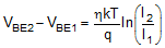
The value η in Equation 1 is a characteristic of the particular transistor used for the remote channel. The POR value for the TMP9R00-SP device is η = 1.008. The value in the η-Factor Correction register can be used to adjust the effective η-factor, according to Equation 2 and Equation 3.
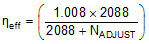

The η-factor correction value must be stored in a two's-complement format, which yields an effective data range from –128 to +127. The POR value for each register is 0000h, which does not affect register values unless a different value is written to the register. The resolution of the η-factor register changes linearly as the code changes and has a range from 0.0004292 to 0.0005476, with an average of 0.0004848.
| NADJUST ONLY BITS 15 TO 8 IN THE REGISTER ARE SHOWN | η | ||
|---|---|---|---|
| BINARY | HEX | DECIMAL | |
| 0111 1111 | 7F | 127 | 0.950205 |
| 0000 1010 | 0A | 10 | 1.003195 |
| 0000 1000 | 08 | 8 | 1.004153 |
| 0000 0110 | 06 | 6 | 1.005112 |
| 0000 0100 | 04 | 4 | 1.006073 |
| 0000 0010 | 02 | 2 | 1.007035 |
| 0000 0001 | 01 | 1 | 1.007517 |
| 0000 0000 | 00 | 0 | 1.008 |
| 1111 1111 | FF | –1 | 1.008483 |
| 1111 1110 | FE | –2 | 1.008966 |
| 1111 1100 | FC | –4 | 1.009935 |
| 1111 1010 | FA | –6 | 1.010905 |
| 1111 1000 | F8 | –8 | 1.011877 |
| 1111 0110 | F6 | –10 | 1.012851 |
| 1000 0000 | 80 | –128 | 1.073829 |