SLUS599B June 2004 – October 2015 TPS2400
PRODUCTION DATA.
- 1 Features
- 2 Applications
- 3 Description
- 4 Revision History
- 5 Pin Configuration and Functions
- 6 Specifications
- 7 Parameter Measurement Information
- 8 Detailed Description
- 9 Application and Implementation
- 10Power Supply Recommendations
- 11Layout
- 12Device and Documentation Support
- 13Mechanical, Packaging, and Orderable Information
Package Options
Refer to the PDF data sheet for device specific package drawings
Mechanical Data (Package|Pins)
- DBV|5
Thermal pad, mechanical data (Package|Pins)
Orderable Information
1 Features
- Up to 100-V Overvoltage Protection
- 6.9-V Overvoltage Shutdown Threshold
- 3-V Undervoltage Shutdown Threshold
- Overvoltage Turnoff Time Less than 1 µs
- External N-Channel MOSFET Driven by Internal Charge Pump
- 1-mA Maximum Static Supply Current
- 5-Pin SOT−23 Package
- −40°C to 85°C Ambient Temperature Range
- 2.5-kV Human-Body-Model, 500-V CDM Electrostatic Discharge Protection
2 Applications
- Cellular Phones
- PDAs
- Portable PCs
- Media Players
- Digital Cameras
- GPS
3 Description
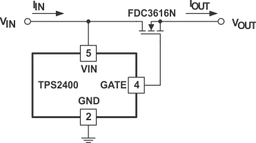
The TPS2400 overvoltage protection controller is used with an external N-channel MOSFET to isolate sensitive electronics from destructive voltage spikes and surges. It is specifically designed to prevent large voltage transients associated with automotive environments (load dump) from damaging sensitive circuitry. When potentially damaging voltage levels are detected by the TPS2400 the supply is disconnected from the load before any damage can occur.
Internal circuitry includes a trimmed band-gap reference, oscillator, Zener diode, charge pump, comparator, and control logic. The TPS2400 device is designed for use with an external N-channel MOSFET, which are readily available in a wide variety of voltages.
Device Information(1)
| PART NUMBER | PACKAGE | BODY SIZE (NOM) |
|---|---|---|
| TPS2400 | SOT-23 (5) | 2.90 mm × 1.60 mm |
- For all available packages, see the orderable addendum at the end of the data sheet.
Application Diagram
