SLVS331I December   2000  – October 2021

PRODUCTION DATA  

  1. Features
  2. Applications
  3. Description
  4. Revision History
  5. Device Comparison Table
    1.     6
  6. Pin Configuration and Functions
  7. Specifications
    1. 7.1 Absolute Maximum Ratings
    2. 7.2 ESD Ratings
    3. 7.3 Recommended Operating Conditions
    4. 7.4 Thermal Information
    5. 7.5 Electrical Characteristics
    6. 7.6 Timing Requirements
    7. 7.7 Switching Characteristics
    8. 7.8 Dissipation Ratings
    9. 7.9 Typical Characteristics
  8. Detailed Description
    1. 8.1 Overview
    2. 8.2 Functional Block Diagram
    3. 8.3 Feature Description
      1. 8.3.1 Input Voltage (VDD)
        1. 8.3.1.1 VDD Hysteresis
        2. 8.3.1.2 VDD Glitch Immunity
      2. 8.3.2 User-Programmable Watchdog Timer (WDI)
      3. 8.3.3 RESET Output
    4. 8.4 Device Functional Modes
      1. 8.4.1 Normal Operation (VDD > VIT)
      2. 8.4.2 Above Power-On Reset But Less Than Threshold (VPOR < VDD < VIT)
      3. 8.4.3 Below Power-On Reset (VDD < VPOR)
    5. 8.5 Programming
      1. 8.5.1 Implementing Window-Watchdog Settings
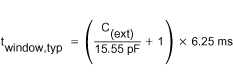
      2. 8.5.2 Programmable Window-Watchdog by Using an External Capacitor
      3. 8.5.3 Lower Boundary Calculation
      4. 8.5.4 Watchdog Software Considerations
      5. 8.5.5 Power-Up Considerations
  9. Application and Implementation
    1. 9.1 Application Information
    2. 9.2 Typical Application
      1. 9.2.1 Design Requirements
      2. 9.2.2 Detailed Design Procedure
      3. 9.2.3 Application Curve
  10. 10Power Supply Recommendations
  11. 11Layout
    1. 11.1 Layout Guidelines
    2. 11.2 Layout Example
  12. 12Device and Documentation Support
    1. 12.1 Related Links
    2. 12.2 Receiving Notification of Documentation Updates
    3. 12.3 Support Resources
    4. 12.4 Trademarks
    5. 12.5 Electrostatic Discharge Caution
    6. 12.6 Glossary
  13. 13Mechanical, Packaging, and Orderable Information

Package Options

Mechanical Data (Package|Pins)
Thermal pad, mechanical data (Package|Pins)
Orderable Information

Programmable Window-Watchdog by Using an External Capacitor

The upper boundary of the watchdog timer can be set by an external capacitor connected between the WDT pin and GND. Common consumer electronic capacitors can be used to implement this feature. They must have low ESR and low tolerances because the tolerances have to be considered if the calculations are performed. The first formula is used to calculate the upper window frame. After calculating the upper window frame, the lower boundary can be calculated. As in the last example, the most important values are the tboundary,max and twindow,min. The trigger pulse has to fit into this window frame.

The external capacitor must have a value between a minimum of 155 pF and a maximum of 63 nF.

Table 8-3 Setting Upper Window Using External Capacitor
SELECTED OPERATION MODE WINDOW FRAME
WDT = external capacitor C(ext) WDR = 0 V and WDR = VDD twindow,max = 1.25 × twindow,typ
twindow,min = 0.75 × twindow,typ
Equation 2. GUID-C70B23CE-ECC8-48C0-A4F6-80B9047D5AB2-low.gif