SLVS790E November 2007 – April 2019 TPS61165
PRODUCTION DATA.
- 1 Features
- 2 Applications
- 3 Description
- 4 Revision History
- 5 Device Options
- 6 Pin Configuration and Functions
- 7 Specifications
- 8 Detailed Description
- 9 Application and Implementation
- 10Power Supply Recommendations
- 11Layout
- 12Device and Documentation Support
- 13Mechanical, Packaging, and Orderable Information
Package Options
Mechanical Data (Package|Pins)
Thermal pad, mechanical data (Package|Pins)
- DRV|6
Orderable Information
9.2.1.2.1 LED Brightness Dimming Mode Selection
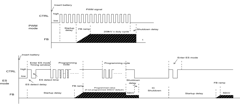
The TPS61165 features two dimming modes: PWM dimming and EasyScale one-wire digital dimming.
The CTRL pin is used for the control input for both dimming modes, PWM dimming and the 1 wire dimming. The dimming mode for the TPS61165 is selected each time the device is enabled. The default dimming mode is PWM dimming. To enter 1 wire mode, the following digital pattern on the CTRL pin must be recognized by the device every time the device starts from the shutdown mode.
- Pull CTRL pin high to enable the TPS61165, and to start the 1 wire detection window.
- After the EasyScale detection delay (tes_delay, 100 μs) expires, drive CTRL low for more than the EasyScale detection time (tes_det, 260 μs). tes_det and tes_delay values are conservative to guarantee the EasyScale detection taking into account the process and clock variations. To ensure not to enter EasyScale mode, please make sure CTRL pin is never held low for more than 160us.
- The CTRL pin has to be low for more than EasyScale detection time before the EasyScale detection window (tes_win, 1 msec) expires. EasyScale detection window starts from the first CTRL pin low to high transition.
The device immediately enters the one-wire mode once the preceding three conditions are met. The EasyScale communication can start before the detection window expires. Once the dimming mode is programmed, it can not be changed without another start up. This means the device needs to be shutdown by pulling the CTRL low for 2.5 ms and restarts. See Figure 9 for a graphical explanation.
 Figure 9. Dimming Mode Detection and Soft Start PWM Brightness Dimming