SLVSET3D March 2020 – October 2020 TPS63900
PRODUCTION DATA
- 1 Features
- 2 Applications
- 3 Description
- 4 Revision History
- 5 Pin Configuration and Functions
- 6 Specifications
-
7 Detailed Description
- 7.1 Overview
- 7.2 Functional Block Diagram
- 7.3 Feature Description
- 7.4 Device Functional Modes
- 8 Application and Implementation
- 9 Power Supply Recommendations
- 10Layout
- 11Device and Documentation Support
- 12Mechanical, Packaging, and Orderable Information
Package Options
Mechanical Data (Package|Pins)
- DSK|10
Thermal pad, mechanical data (Package|Pins)
- DSK|10
Orderable Information
8.2.3 Application Curves
Table 8-5 Components for Application
Characteristic Curves for VOUT = 3.3 V
| REFERENCE(1) | DESCRIPTION(2) | PART NUMBER | MANUFACTURER |
|---|---|---|---|
| U1 | 400-mA ultra low Iq Buck-Boost Converter (2.5 mm x 2.5 mm QFN) | TPS63900DSK | Texas Instruments |
| L1 | 2.2 µH, 2.5 mm x 2 mm x 1.2 mm, 3.3 A, 82 mΩ | DFE252012F-2R2M | Murata |
| C1 | 10 µF, 0603, Ceramic Capacitor, ±20%, 6.3 V | GRM188R60J106ME47 | Murata |
| C2 | 22 µF, 0603, Ceramic Capacitor, ±20%, 6.3 V | GRM187R60J226ME15 | Murata |
| CFG1 | 36.5 kΩ, 0603 Resistor, 1%, 100 mW | Standard | Standard |
| CFG2 | 0 Ω, 0603 Resistor, 1%, 100 mW | Standard | Standard |
| CFG3 | 0 Ω, 0603 Resistor, 1%, 100 mW | Standard | Standard |
(1) See Third-Party Products Discalimer
(2) For other output voltages, refer to Table 8-1 for resistor values.
Table 8-6 Typical Characteristics
Curves
| PARAMETER | CONDITIONS | FIGURE |
|---|---|---|
| Output Current Capability | ||
| Typical Output Current Capability versus Input Voltage | VO = 1.8 V to 5.0 V | Figure 8-2 |
| Switching Frequency | ||
| Typical Burst Switching Frequency versus Output Current | VI = 3.3 V, VO = 1.8 V to 5.0 V | Figure 8-3 |
| Typical Burst Switching Frequency versus Output Current | VI = 2.0 V, VO = 1.8 V to 5.0 V | Figure 8-4 |
| Typical Burst Switching Frequency versus Output Current | VI = 5.2 V, VO = 1.8 V to 5.0 V | Figure 8-5 |
| Efficiency | ||
| Efficiency versus Output Current | VI = 1.8 V to 5.5 V, VO = 1.8 V | Figure 8-6 |
| Efficiency versus Output Current | VI = 1.8 V to 5.5 V, VO = 3.3 V | Figure 8-7 |
| Efficiency versus Output Current | VI = 1.8 V to 5.5 V, VO = 5.0 V | Figure 8-8 |
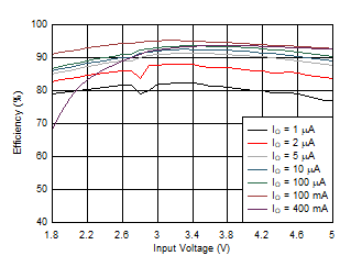
| Efficiency versus Input Voltage | IO = 1 μA to 400 mA, VO = 3.3 V | Figure 8-9 |
| Switching Waveforms | ||
| Switching Waveforms, Boost Operation | VI = 1.8 V, VO = 3.3 V | Figure 8-10 |
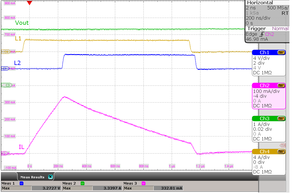
| Switching Waveforms, Boost Operation | VI = 2.8 V, VO = 3.3 V | Figure 8-11 |
| Switching Waveforms, Buck-Boost Operation | VI = 3.3 V, VO = 3.3 V | Figure 8-12 |
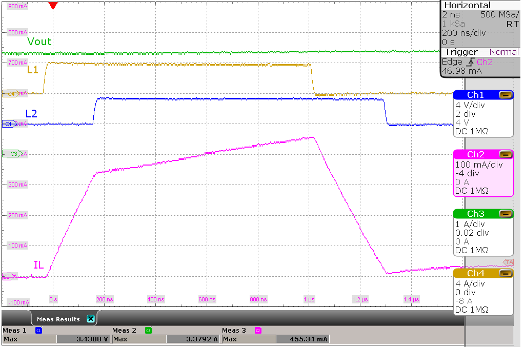
| Switching Waveforms, Buck Operation | VI = 4.0 V, VO = 3.3 V | Figure 8-13 |
| Output Voltage Ripple | ||
| Output Voltage Ripple | VI = 2.0 V, VO = 1.8 V to 5.0 V | Figure 8-14 |
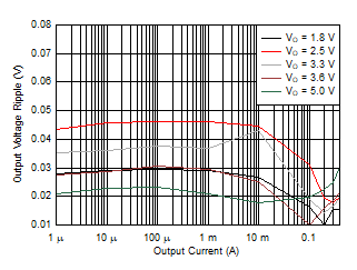
| Output Voltage Ripple | VI = 3.3 V, VO = 1.8 V to 5.0 V | Figure 8-15 |
| Output Voltage Ripple | VI = 5.2 V, VO = 1.8 V to 5.0 V | Figure 8-16 |
| Output Voltage Ripple over Temperature | VI = 3.3 V, VO = 3.6 V | Figure 8-17 |
| Regulation Accuracy | ||
| Load Regulation | VO = 3.3 V | Figure 8-18 |
| Line Regulation | VI = 1.8 V to 5.0 V, Load = 1 mA | Figure 8-19 |
| Transient Performance | ||
| Line Transient, Light Load | VI = 2.5 V to 4.2 V, VO = 3.3 V, Load = 1 mA | Figure 8-20 |
| Line Transient, High Load | VI = 2.5 V to 4.2 V, VO = 3.3 V, Load = 100 mA | Figure 8-21 |
| Load Transient, 100 mA Step | VI = 1.8 V, VO = 3.3 V, Load = 0 mA to 100 mA | Figure 8-22 |
| Load Transient, 100 mA Step | VI = 3.3 V, VO = 3.3 V, Load = 0 mA to 100 mA | Figure 8-23 |
| Load Transient, 100 mA Step | VI = 1.8 V, VO = 3.3 V, Load = 0 mA to 100 mA | Figure 8-24 |
| Load Transient, 300 mA Step | VI = 3.3 V, VO = 1.8 V, Load = 0 mA to 300 mA | Figure 8-25 |
| Load Transient, 300 mA Step | VI = 3.3 V, VO = 3.3 V, Load = 0 mA to 300 mA | Figure 8-26 |
| Load Transient, 300 mA Step | VI = 5.5 V, VO = 3.3 V, Load = 0 mA to 300 mA | Figure 8-27 |
| Start-up | ||
| Start-up Behavior from Rising Enable | VI = 3.3 V, VO = 3.3 V, Load = 100 mA | Figure 8-28 |
| Start-up Behavior from Rising Enable | VI = 1.8 V, VO = 1.8 V, Load = 10 μA | Figure 8-29 |
| Start-up Behavior from Rising Enable | VI = 1.8 V, VO = 5.0 V, Load = 10 μA | Figure 8-30 |
| Start-up Behavior from Rising Enable | VI = 1.8 V, VO = 5.0 V, Load = 1000 μF | Figure 8-31 |
| ICL (Input Current Limit) | ||
| Start-up with 1 mA ICL | VI = 3.3 V, VO = 3.3 V, CO = 300 μF | Figure 8-32 |
| Start-up with 2.5 mA ICL | VI = 3.3 V, VO = 3.3 V, CO = 300 μF | Figure 8-33 |
| Start-up with 5 mA ICL | VI = 3.3 V, VO = 3.3 V, CO = 300 μF | Figure 8-34 |
| Start-up with 10 mA ICL | VI = 3.3 V, VO = 3.3 V, CO = 300 μF | Figure 8-35 |
| Start-up with 25 mA ICL | VI = 3.3 V, VO = 3.3 V, CO = 300 μF | Figure 8-36 |
| Start-up with 50 mA ICL | VI = 3.3 V, VO = 3.3 V, CO = 300 μF | Figure 8-37 |
| Start-up with 100 mA ICL | VI = 3.3 V, VO = 3.3 V, CO = 300 μF | Figure 8-38 |
| Short Circuit Behavior | ||
| Short Circuit Behavior | VI = 3.3 V, VO = 1.8 V | Figure 8-39 |
| Short Circuit Behavior | VI = 3.3 V, VO = 3.3 V | Figure 8-40 |
| Short Circuit Behavior | VI = 3.3 V, VO = 5.0 V | Figure 8-41 |
| DVS (Digital Voltage Scaling) | ||
| DVS Behavior at Light Load | VI = 3.3 V, VO(1) = 2.2 V, VO(2) = 3.6 V, Load = 1 kΩ | Figure 8-42 |
| DVS Behavior at High Load | VI = 3.3 V, VO(1) = 2.2 V, VO(2) = 3.6 V, Load = 30 Ω | Figure 8-43 |
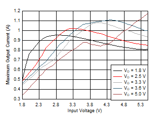
| TA = 25°C |
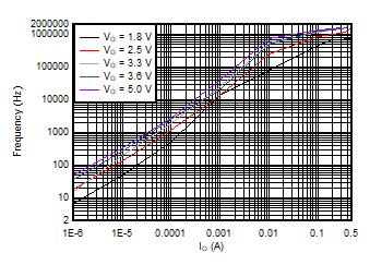
| VI = 2.0 V | TA = 25°C | |
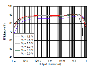
| VO = 1.8 V | TA = 25°C | |
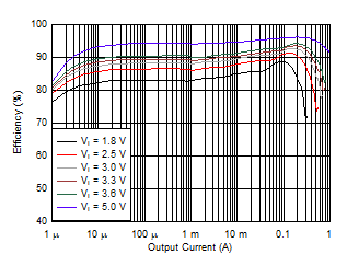
| VO = 5.0 V | TA = 25°C | |
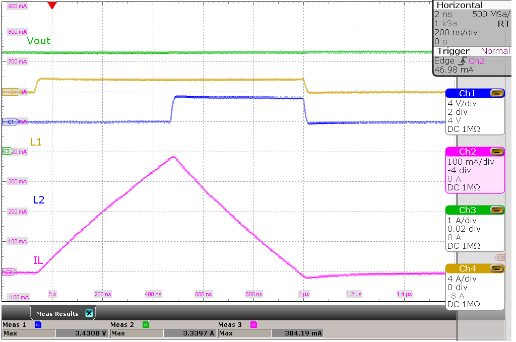
| VI = 1.8 V, VO = 3.3 V | No load | |
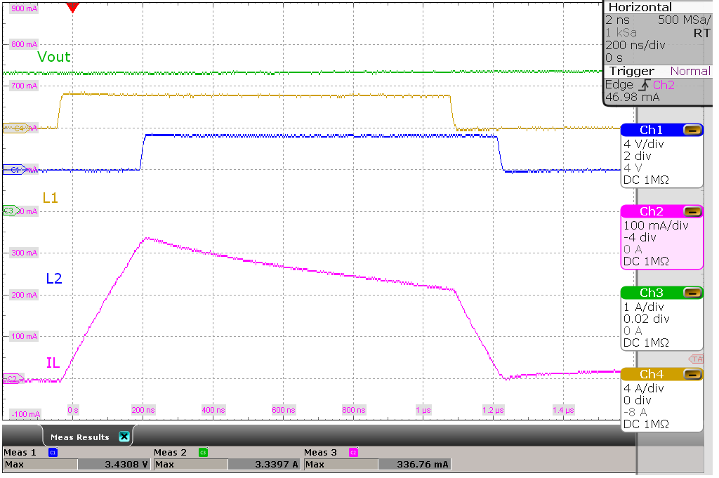
| VI = 3.3 V, VO = 3.3 V | No load | |
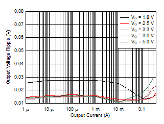
| VI = 2.0 V | TA = 25°C | |
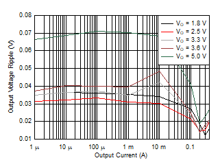
| VI = 5.2 V | TA = 25°C | |
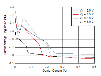
| VO = 3.3 V | TA = 25°C | |
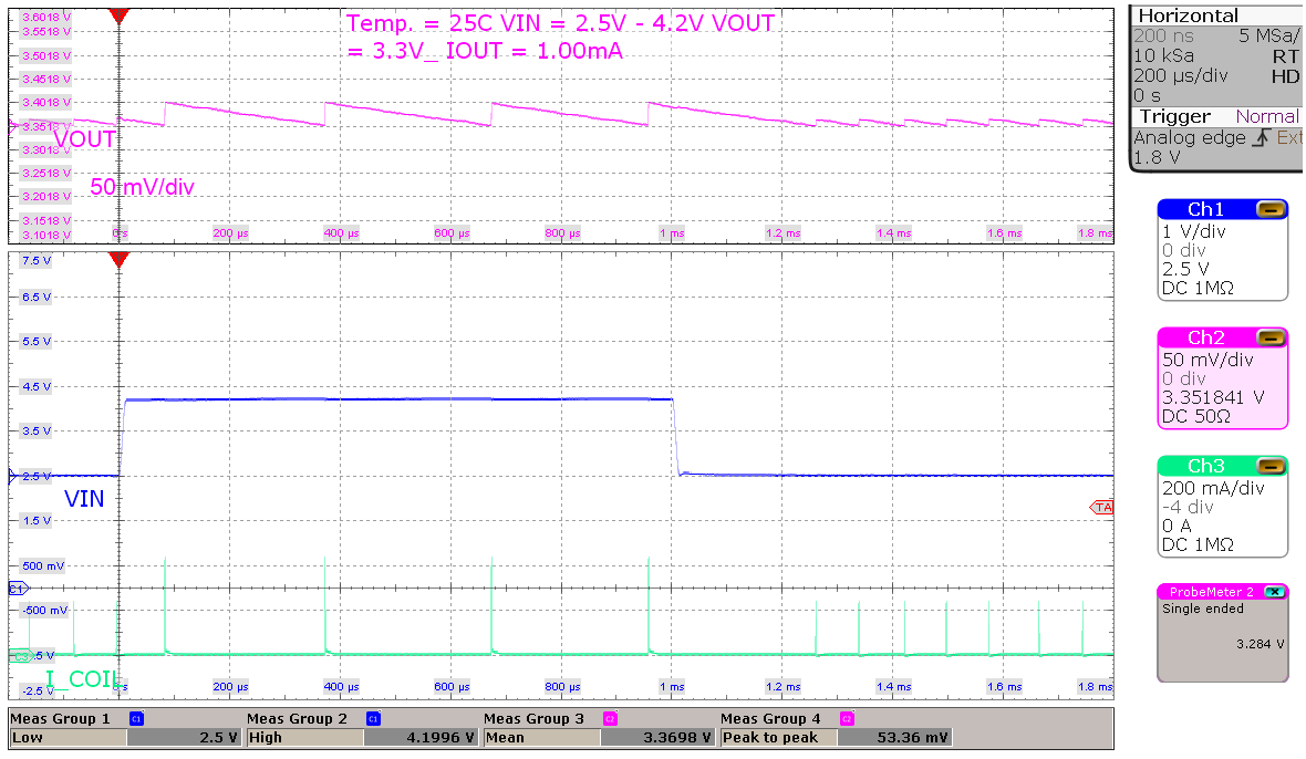
| VI = 2.5 V to 4.2 V, VO = 3.3V | Load = 1 mA | |
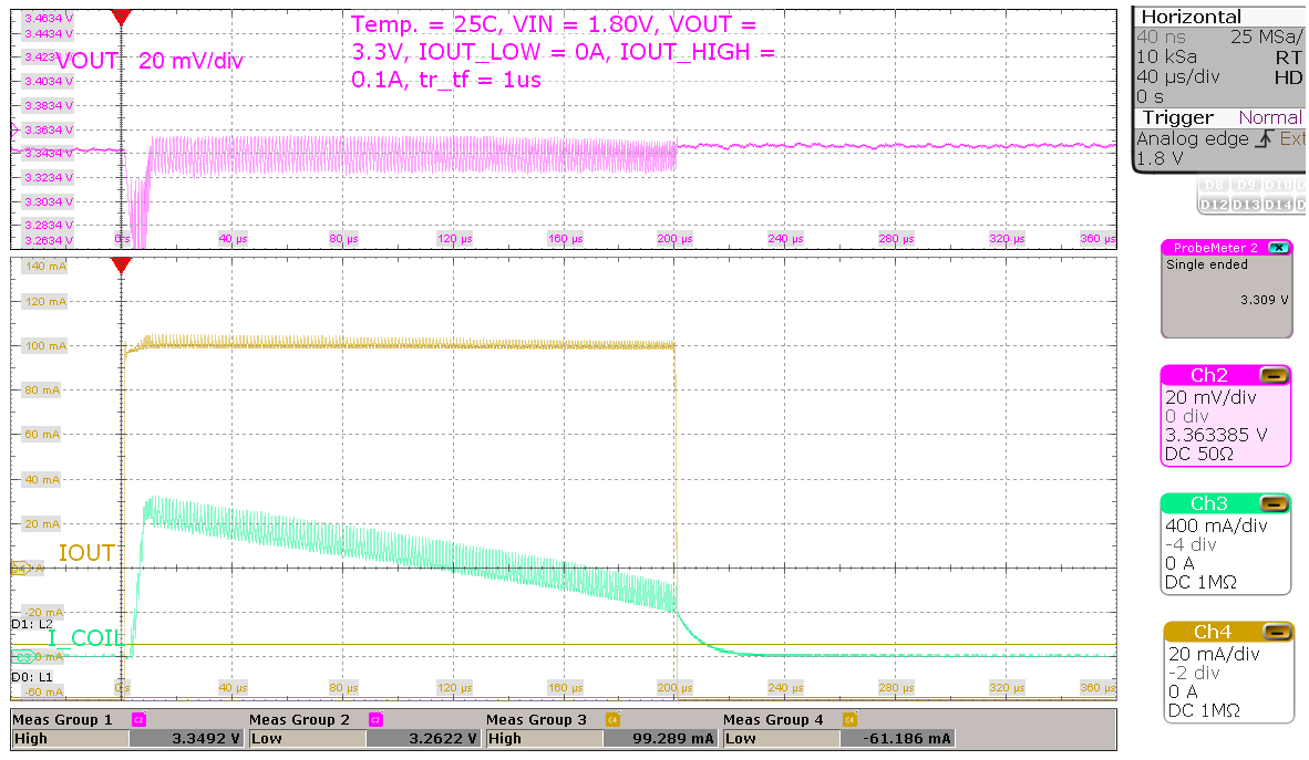
| VI = 1.8 V, VO = 3.3 V | Load = 0 mA to 100 mA, tr/tf = 1 μs | |
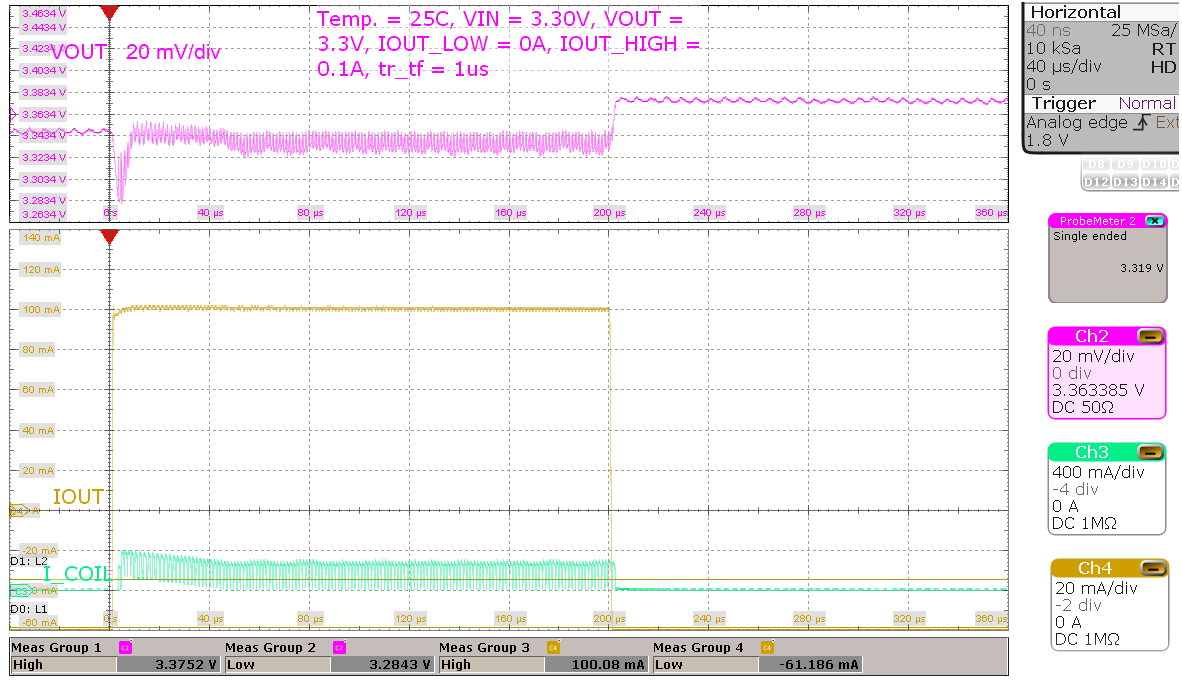
| VI = 3.3 V, VO = 3.3 V | Load = 0 mA to 100 mA, tr/tf = 1 μs | |
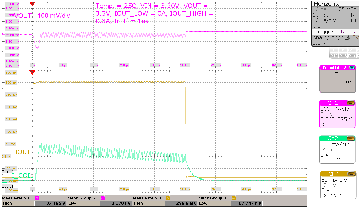
| VI = 3.3 V, VO = 3.3 V | Load = 0 mA to 300 mA, tr/tf = 1 μs | |
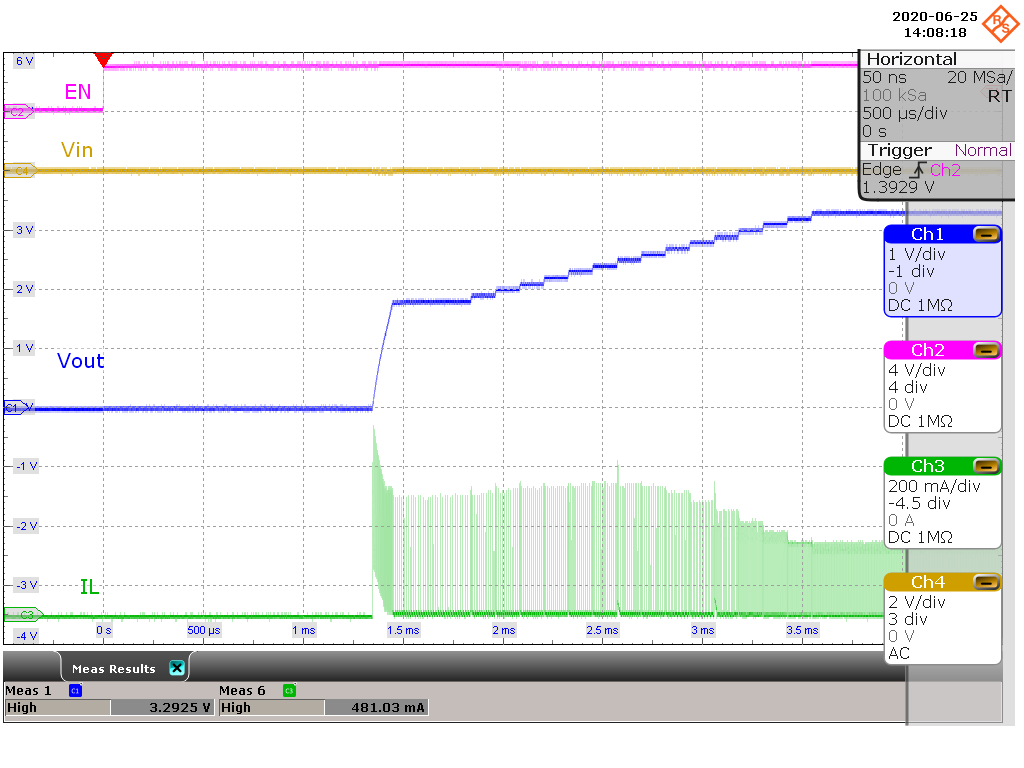
| VI = 3.3 V, VO = 3.3 V | 100-mA resistive load | |
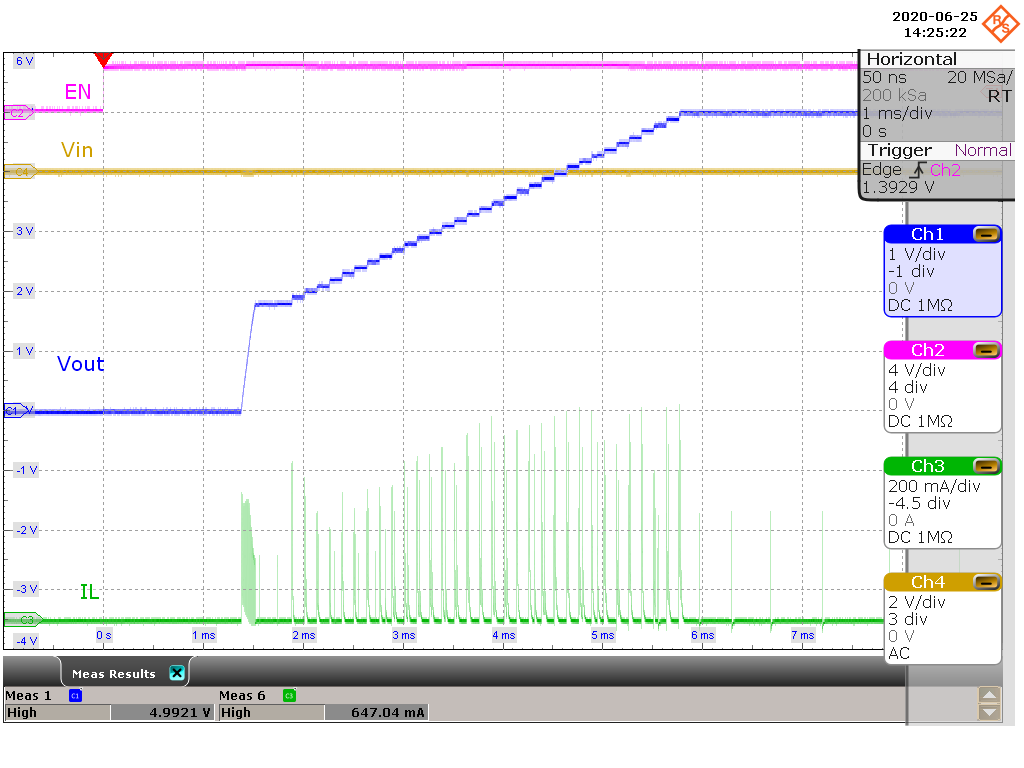
| VI = 1.8 V, VO = 5.0 V | 10-μA resistive load | |
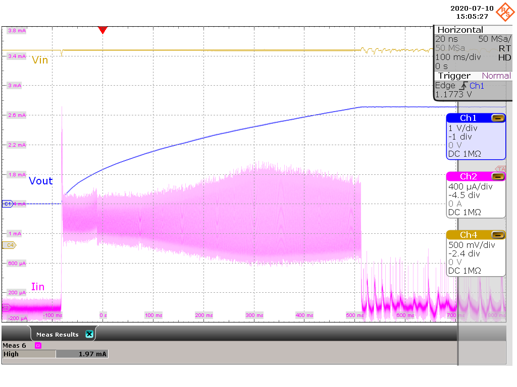
| VI = 3.3 V, VO = 3.3 V | CI = 32 μF, CO = 300 μF | |
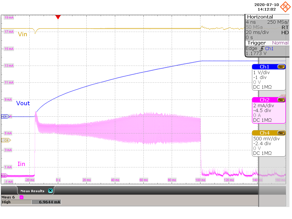
| VI = 3.3 V, VO = 3.3 V | CI = 32 μF, CO = 300 μF | |
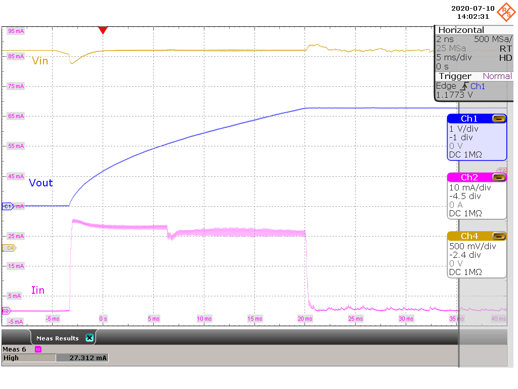
| VI = 3.3 V, VO = 3.3 V | CI = 32 μF, CO = 300 μF | |
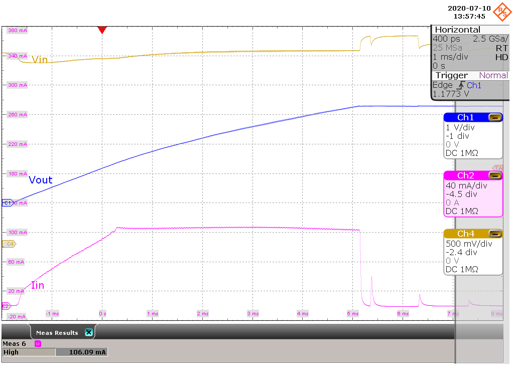
| VI = 3.3 V, VO = 3.3 V | CI = 32 μF, CO = 300 μF | |
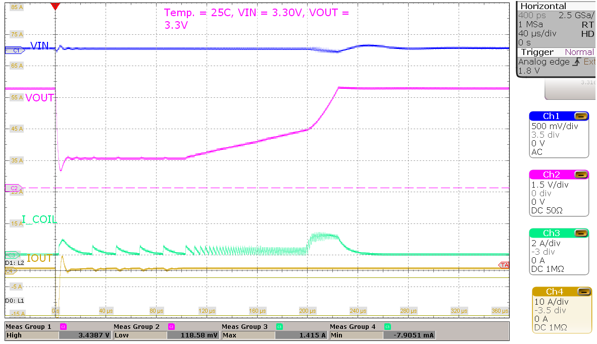
| VI = 3.3 V, VO = 3.3 V | TA = 25°C | |
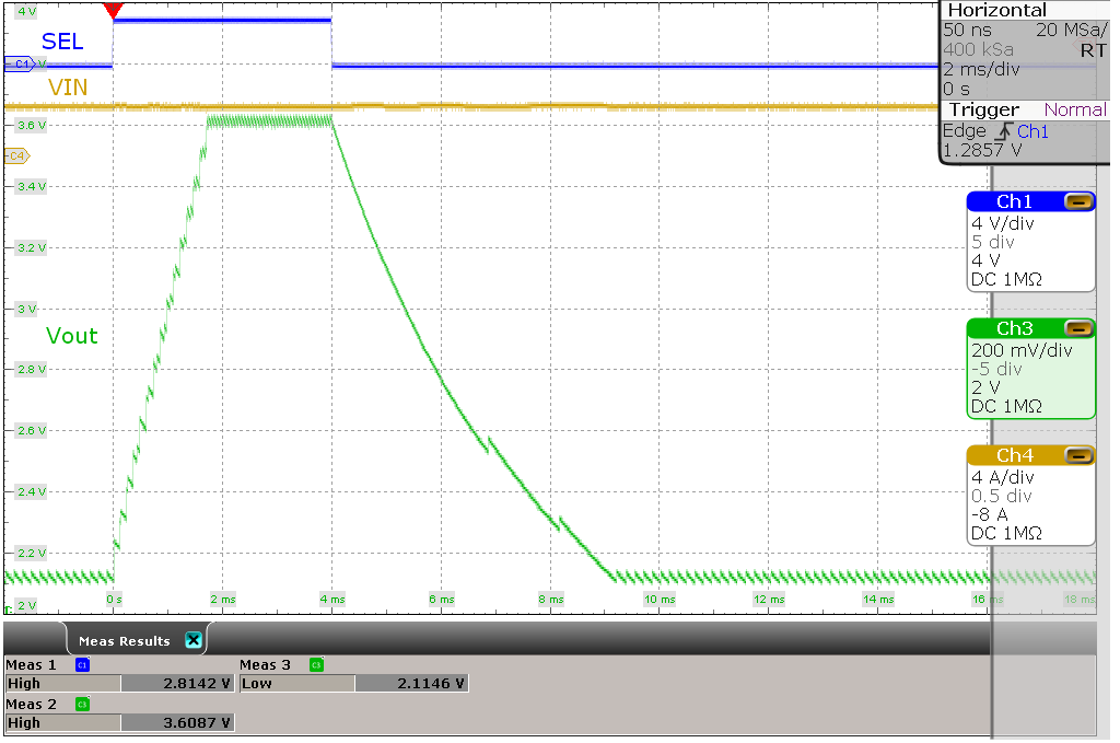
| VI = 3.3 V, VO(1) = 2.2 V, VO(2) = 3.6 V | 1-kΩ resistive load | |
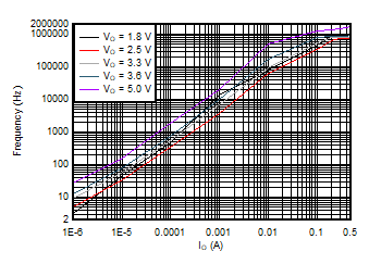
| VI = 3.3 V | TA = 25°C | |
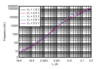
| VI = 5.2 V | TA = 25°C | |
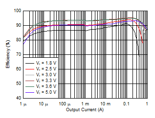
| VO = 3.3 V | TA = 25°C | |
| VO = 3.3 V | TA = 25°C | |
| VI = 2.8 V, VO = 3.3 V | No load | |
| VI = 4.0 V, VO = 3.3 V | No load | |
| VI = 3.3 V | TA = 25°C | |
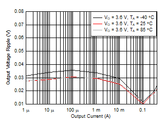
| VI = 3.3 V, VO = 3.6 V |
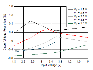
| VI = 1.8 V to 5.0 V | Load = 1 mA, TA = 25°C | |
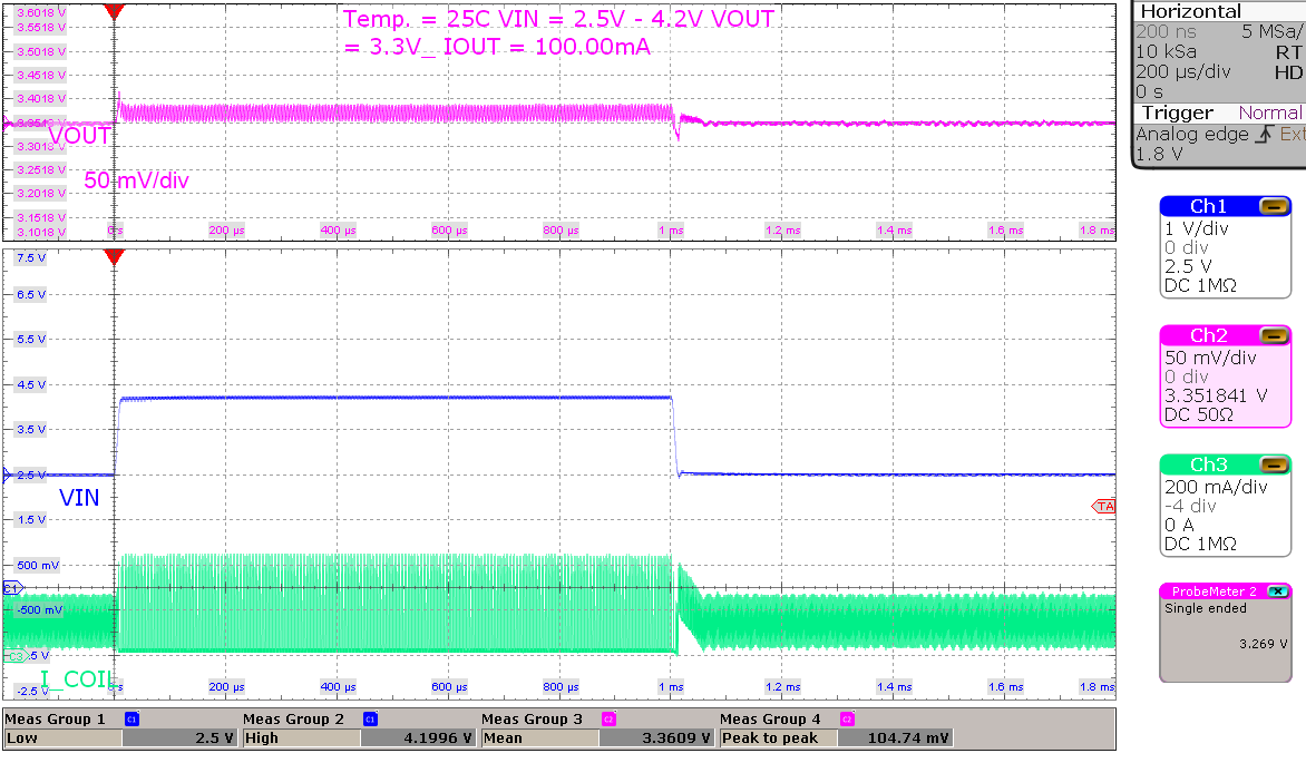
| VI = 2.5 V to 4.2 V, VO = 3.3 V | Load = 100 mA | |
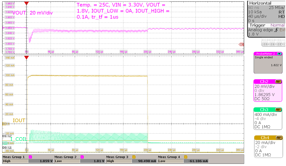
| VI = 3.3 V, VO = 1.8 V | Load = 0 mA to 100 mA, tr/tf = 1 μs | |
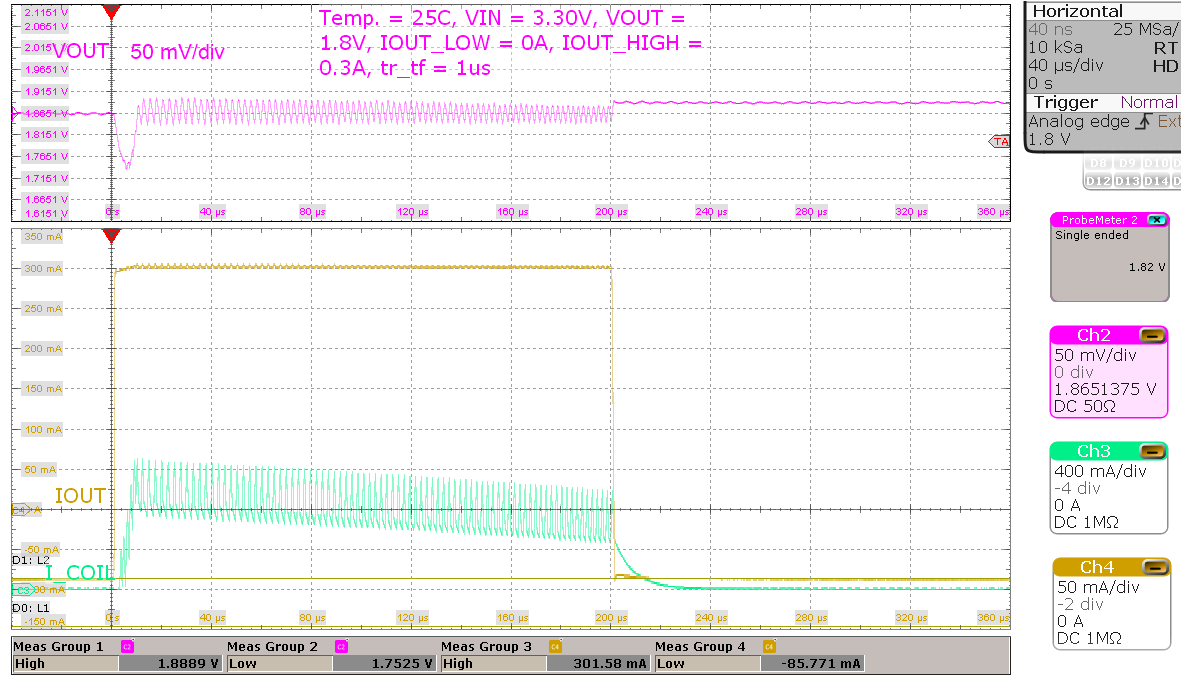
| VI = 3.3 V, VO = 1.8 V | Load = 0 mA to 300 mA, tr/tf = 1 μs | |
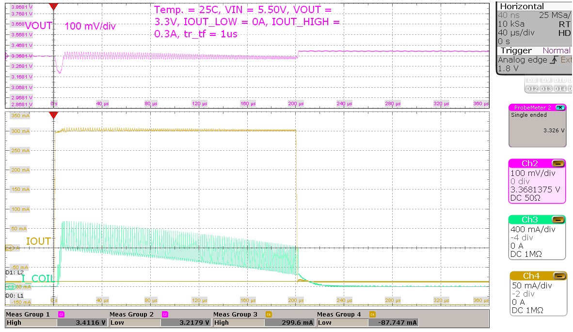
| VI = 5.5 V, VO = 3.3 V | Load = 0 mA to 300 mA, tr/tf = 1 μs | |
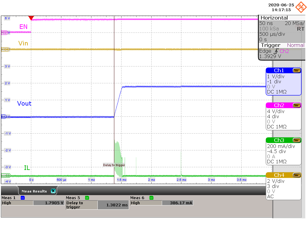
| VI = 1.8 V, VO = 1.8 V | 10-μA resistive load | |
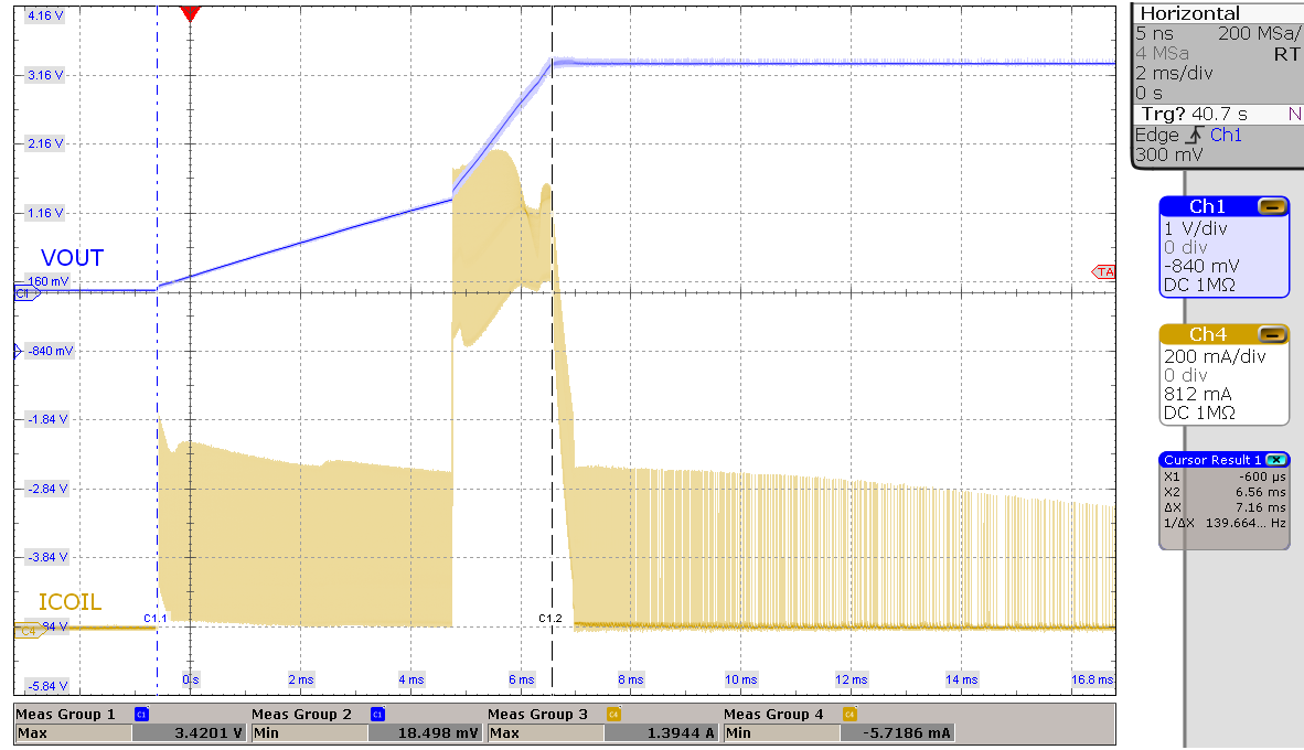
| VI = 3.3 V, VO = 3.3 V | 1000-μF capacitive load | |
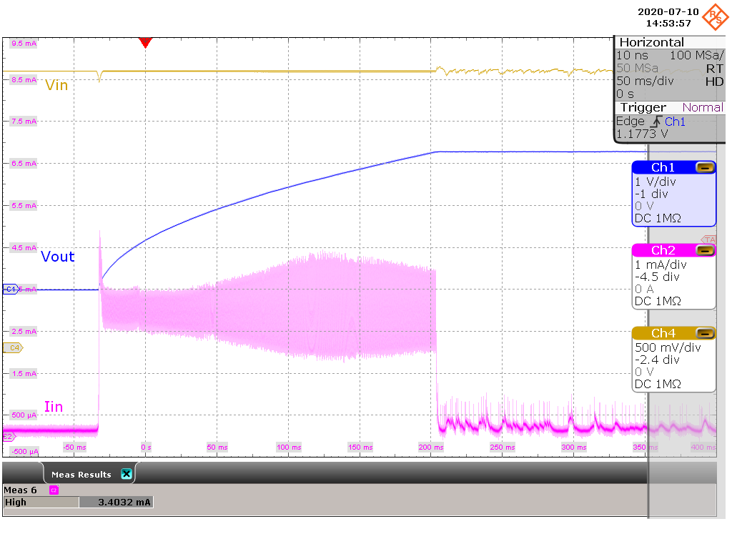
| VI = 3.3 V, VO = 3.3 V | CI = 32 μF, CO = 300 μF | |
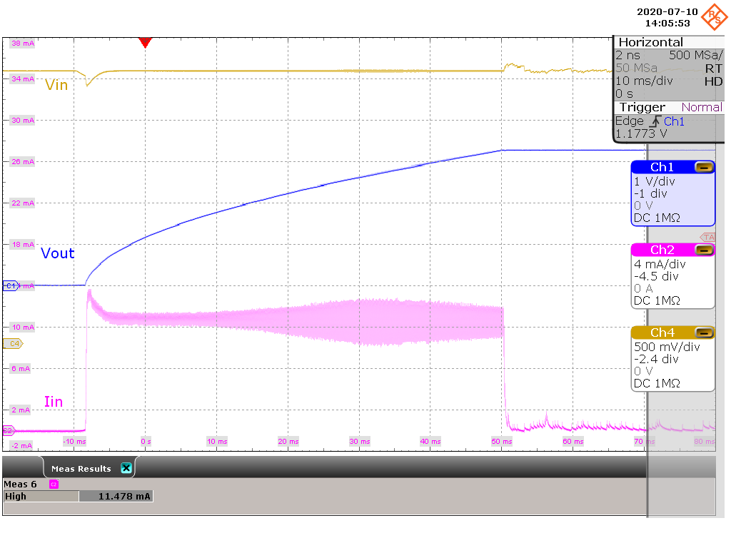
| VI = 3.3 V, VO = 3.3 V | CI = 32 μF, CO = 300 μF | |
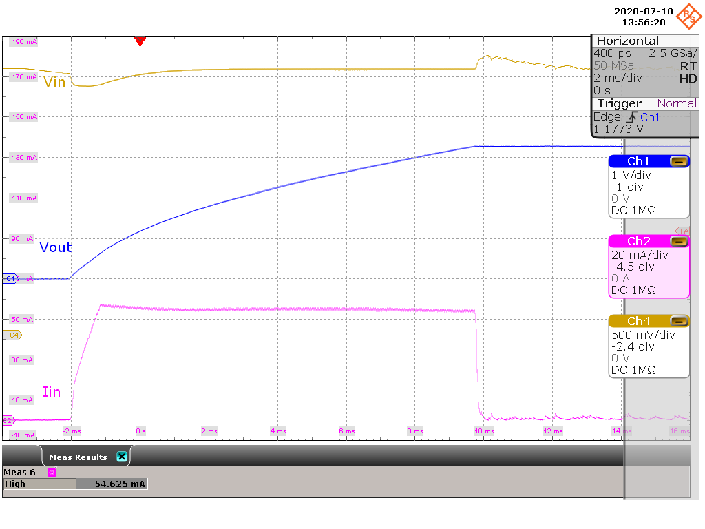
| VI = 3.3 V, VO = 3.3 V | CI = 32 μF, CO = 300 μF | |
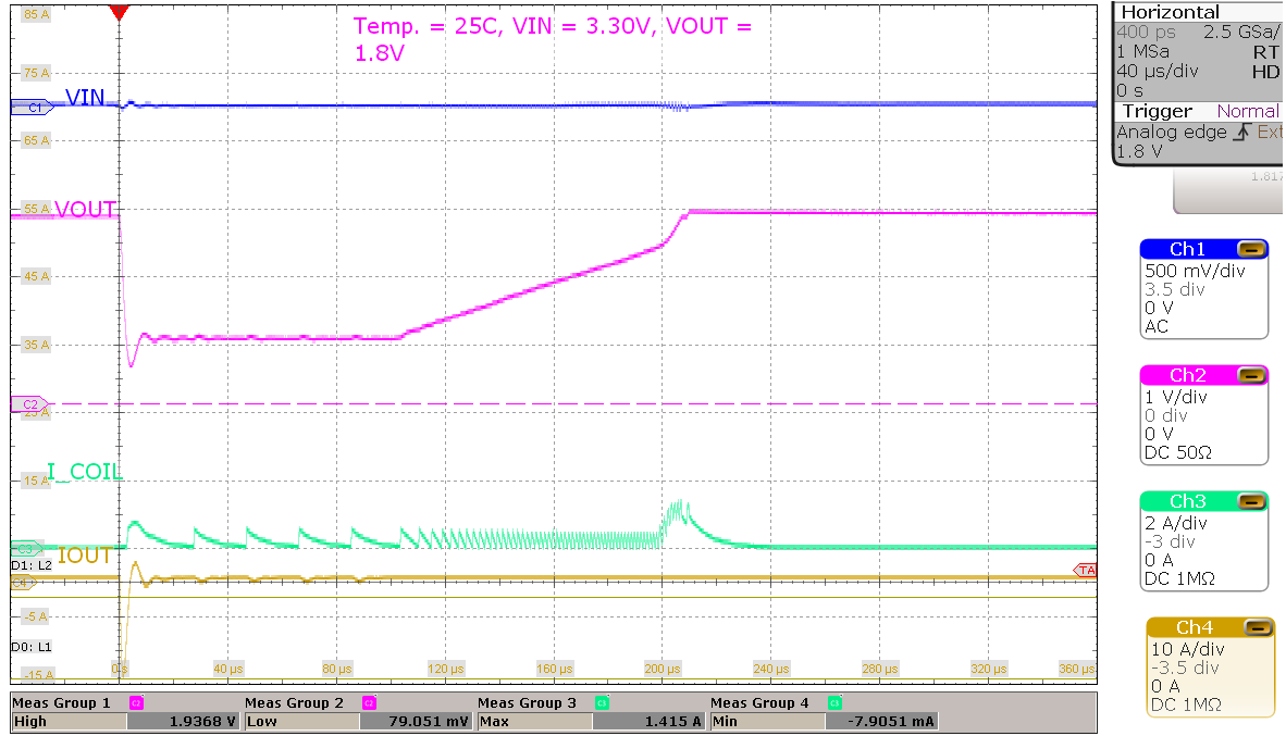
| VI = 3.3 V, VO = 1.8 V | TA = 25°C | |
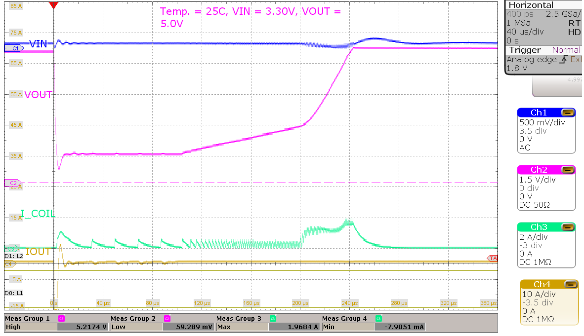
| VI = 3.3 V, VO = 5.0 V | TA = 25°C | |
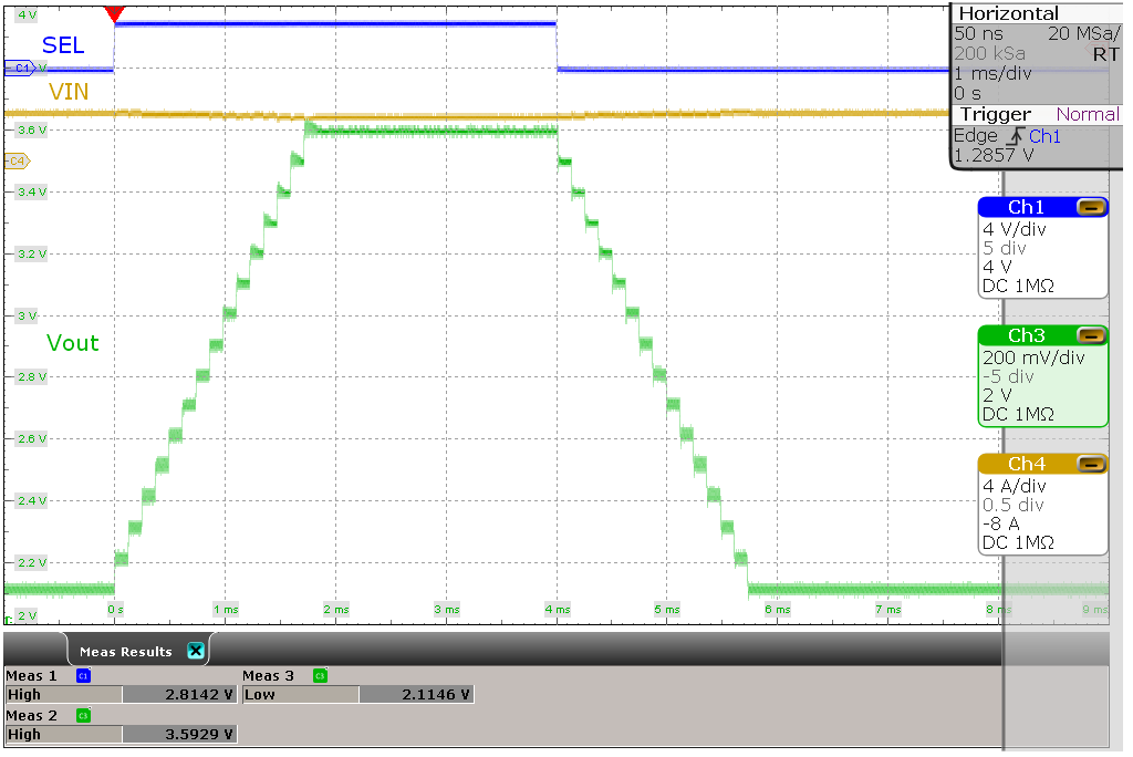
| VI = 3.3 V, VO(1) = 2.2 V, VO(2) = 3.6 V | 30-Ω resistive load | |