SLVSEW6F August 2021 – March 2024 TPS7H2211-SEP , TPS7H2211-SP
PRODUCTION DATA
- 1
- 1 Features
- 2 Applications
- 3 Description
- 4 Device Options
- 5 Related Products
- 6 Pin Configuration and Functions
-
7 Specifications
- 7.1 Absolute Maximum Ratings
- 7.2 ESD Ratings
- 7.3 Recommended Operating Conditions
- 7.4 Thermal Information
- 7.5 Electrical Characteristics: All Devices
- 7.6 Electrical Characteristics: CFP and KGD Options
- 7.7 Electrical Characteristics: HTSSOP Option
- 7.8 Switching Characteristics: All Devices
- 7.9 Quality Conformance Inspection
- 7.10 Typical Characteristics
- 8 Parameter Measurement Information
- 9 Detailed Description
- 10Application and Implementation
- 11Device and Documentation Support
- 12Revision History
- 13Mechanical, Packaging, and Orderable Information
Package Options
Refer to the PDF data sheet for device specific package drawings
Mechanical Data (Package|Pins)
- DAP|32
- KGD|0
- HKR|16
Thermal pad, mechanical data (Package|Pins)
- DAP|32
Orderable Information
10.2.2.2.4 Soft Start Time
The desired 1-ms soft start time is achieved following the procedure in Section 9.3.3. The procedure is replicated below for convenience.
First, use Equation 23 to determine the needed value of CSS. This results in a calculated CSS value of 16.3 nF. A 22-nF ±10% capacitor is selected.
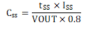
where
- tSS = 1 ms = 1 × 10⁻³ s
- ISS(TYP) = 65 μA = 65 × 10–6 A
- VOUT(NOM) = 5 V
Next determine the resulting slew rate using Equation 24. Using the minimum value for the 10% tolerance CSS and the maximum value for ISS results in the worst case (fastest) slew rate of 4,192 V/s.
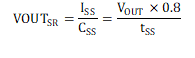
where
- ISS(MAX) = 83 μA = 83 × 10–6 A
- CSS = 22 nF × (1 – 10%) = 19.8 × 10⁻⁹ F
Finally, determine if the resulting slew rate is less than the maximum allowed by Equation 25. IL_trip is typically 8.5 A, but in order to select a conservative value it is suggested to let IL_trip = 5.4 A (which is also the absolute maximum rating for continuous switch current). The 2,955-V/s slew rate is less than the maximum acceptable slew rate of 4,192 V/s. Therefore, this soft start capacitor is acceptable.
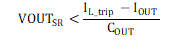
where
- IL_trip = 5.4 A
- IOUT(NOM) = 3.0 A
- COUT = 170.1 μF = 170.1 × 10⁻⁶ F
While it is typically trivial to meet the slew rate restrictions (as demonstrated here by selecting a relatively fast soft start time), note that for space applications a large output capacitor is often utilized. This results in a lower maximum acceptable slew rate and additional care must be taken in order to ensure the expected slew rate is not too fast.