SLVSEW6F August 2021 – March 2024 TPS7H2211-SEP , TPS7H2211-SP
PRODUCTION DATA
- 1
- 1 Features
- 2 Applications
- 3 Description
- 4 Device Options
- 5 Related Products
- 6 Pin Configuration and Functions
-
7 Specifications
- 7.1 Absolute Maximum Ratings
- 7.2 ESD Ratings
- 7.3 Recommended Operating Conditions
- 7.4 Thermal Information
- 7.5 Electrical Characteristics: All Devices
- 7.6 Electrical Characteristics: CFP and KGD Options
- 7.7 Electrical Characteristics: HTSSOP Option
- 7.8 Switching Characteristics: All Devices
- 7.9 Quality Conformance Inspection
- 7.10 Typical Characteristics
- 8 Parameter Measurement Information
- 9 Detailed Description
- 10Application and Implementation
- 11Device and Documentation Support
- 12Revision History
- 13Mechanical, Packaging, and Orderable Information
Package Options
Refer to the PDF data sheet for device specific package drawings
Mechanical Data (Package|Pins)
- DAP|32
- KGD|0
- HKR|16
Thermal pad, mechanical data (Package|Pins)
- DAP|32
Orderable Information
9.3.3 Soft Start (Adjustable Rise Time)
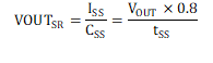
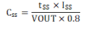
An external capacitor, CSS, connected between the VOUT and SS pins, sets tSS, the soft start time. tSS is defined as the time it takes VOUT to rise from 10% to 90% of its final value. Equation 13 calculates the needed CSS capacitor where ISS is the soft start current (typically 65 μA) and VOUT is the final output voltage reached (for example, 12 V).
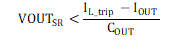
In order to avoid false trips due to the internal current limit being triggered during startup, the slew rate VOUTSR, must satisfy Equation 15 where IL_trip is the internal current limit trip point (typically 8.5 A), IOUT is the final output current (max of 3.5 A), and COUT is the output capacitance. In the Application and Implementation Soft Start Time section, a suggested derated value for IL_TRIP is shown.
If external current limit circuitry is used, it is recommended to replace the IL_trip value with the minimum trip-point value of the external current limit (assuming this trip-point is less than IL_trip). This is in order to ensure the external current limit circuitry isn't tripped during startup.
The output slew rate of the eFuse, VOUTSR, can be calculated as shown in Equation 14. To determine the worst case slew rate, it is recommended to use the maximum value of ISS, 83 μA, and the minimum value of the selected capacitor. These worst case conditions may also be used to calculate the worst case (fastest) tSS time.