SLVSCK5C September   2014  – January 2020 TPS92638-Q1

PRODUCTION DATA.  

  1. Features
  2. Applications
  3. Description
  4. Typical Application Schematic
  5. Revision History
  6. Pin Configuration and Functions
    1.     Pin Functions
  7. Specifications
    1. 7.1 Absolute Maximum Ratings
    2. 7.2 ESD Ratings
    3. 7.3 Recommended Operating Conditions
    4. 7.4 Thermal Information
    5. 7.5 Electrical Characteristics
    6. 7.6 Switching Characteristics
    7. 7.7 Typical Characteristics
  8. Parameter Measurement Information
  9. Detailed Description
    1. 9.1 Overview
    2. 9.2 Functional Block Diagram
    3. 9.3 Feature Description
      1. 9.3.1 LED Current Setting
      2. 9.3.2 PWM Control
      3. 9.3.3 Fault Diagnostics
        1. 9.3.3.1 Open-Load Detection
      4. 9.3.4 Thermal Foldback
    4. 9.4 Device Functional Modes
  10. 10Application and Implementation
    1. 10.1 Application Information
    2. 10.2 Typical Applications
      1. 10.2.1 PWM Dimming by Bank
        1. 10.2.1.1 Design Requirements
        2. 10.2.1.2 Detailed Design Procedure
        3. 10.2.1.3 Application Performance Plots
      2. 10.2.2 Two Brightness Levels for TAIL and STOP Lights
        1. 10.2.2.1 Design Requirements
        2. 10.2.2.2 Detailed Design Procedure
      3. 10.2.3 PWM Dimming by Modulated Supply
        1. 10.2.3.1 Design Requirements
        2. 10.2.3.2 Design Procedure
      4. 10.2.4 Driving LEDs From a Single Device With Channels in Parallel
        1. 10.2.4.1 Design Requirements
        2. 10.2.4.2 Design Procedure
      5. 10.2.5 Driving LEDs From Multiple Devices With Channels in Parallel
        1. 10.2.5.1 Design Requirements
        2. 10.2.5.2 Design Procedure
  11. 11Power Supply Recommendations
  12. 12Layout
    1. 12.1 Layout Guidelines
    2. 12.2 Layout Example
    3. 12.3 Thermal Information
  13. 13Device and Documentation Support
    1. 13.1 Trademarks
    2. 13.2 Electrostatic Discharge Caution
    3. 13.3 Glossary
  14. 14Mechanical, Packaging, and Orderable Information

Package Options

Mechanical Data (Package|Pins)
Thermal pad, mechanical data (Package|Pins)
Orderable Information

Typical Characteristics

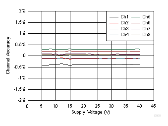
TPS92638-Q1 D005_SLVSCK5.gif
Figure 1. I(IOUTx) Accuracy vs V(SUPPLY)
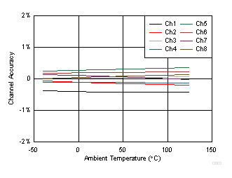
TPS92638-Q1 D003_SLVSCK5.gif
V(SUPPLY) = 5 V
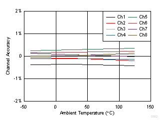
Figure 3. I(IOUTx) Accuracy vs Ambient Temperature
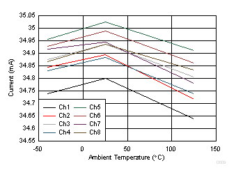
TPS92638-Q1 D009_SLVSCK5.gif
V(SUPPLY) = 12 V
Figure 5. I(IOUTx) Current vs Temperature
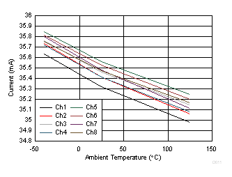
TPS92638-Q1 D011_SLVSCK5.gif
V(SUPPLY) = 40 V
Figure 7. I(IOUTx) Current vs Temperature
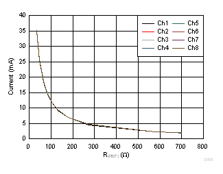
TPS92638-Q1 D008_SLVSCK5.gif
Figure 9. I(IOUTx) Current vs R(REF)
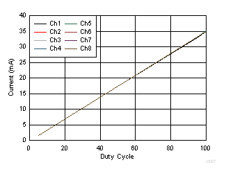
TPS92638-Q1 D007_SLVSCK5.gif
Figure 11. I(IOUTx) Current vs PWM Duty Cycle
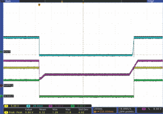
TPS92638-Q1 scope_p27_slvsck5.gif
CH1: V(IOUT1) CH2: I(IOUT1) CH3: V(SUPPLY)
CH4: FAULT
Figure 13. Cold Cranking Behavior
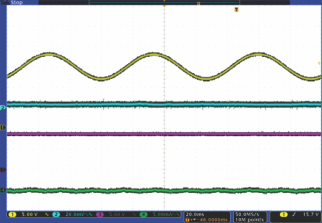
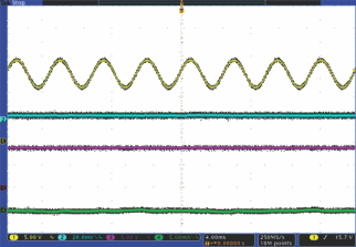
TPS92638-Q1 scope_p29_slvsck5.gif
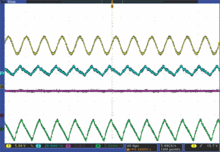
CH1: V(SUPPLY) CH2: V(REF) CH3: V(IOUT8)
CH4: I(IOUT8) I(IOUTx) = 35 mA
Figure 15. Superimposed Alternating Voltage, 12 V–18 V, 15 Hz
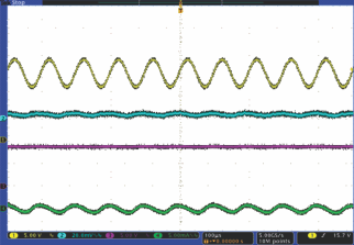
TPS92638-Q1 scope_p31_slvsck5.gif
CH1: V(SUPPLY) CH2: V(REF) CH3: V(IOUT8)
CH4: I(IOUT8) I(IOUTx) = 35 mA
Figure 17. Superimposed Alternating Voltage, 12 V–18 V, 2 kHz
TPS92638-Q1 scope_p33_slvsck5.gif
CH1: V(SUPPLY) CH2: V(REF) CH3: V(IOUT8)
CH4: I(IOUT8) I(IOUTx) = 35 mA
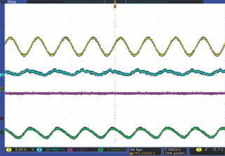
Figure 19. Superimposed Alternating Voltage, 12 V–18 V, 20 kHz
TPS92638-Q1 scope_p35_slvsck5.gif
CH1: V(IOUT1) CH2: I(IOUT1) CH3: V(SUPPLY)
CH4: I(FAULT)
Figure 21. Transient Overvoltage (16 V – 18 V – 17 V – 16 V)
TPS92638-Q1 scope_p37_slvsck5.gif
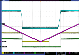
CH1: V(IOUT1) CH2: I(IOUT1) CH3: V(SUPPLY)
CH4: I(FAULT)
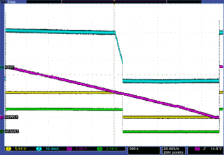
Figure 23. Slow Decrease and Quick Increase
TPS92638-Q1 scope_p39_slvsck5.gif
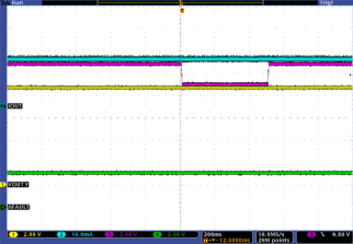
CH1: V(SUPPLY) CH2: V(FAULT) CH3: V(REF)
CH4: I(IOUT8)
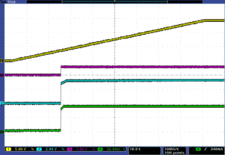
Figure 25. Slow Power Up (V(SUPPLY), V(EN), V(PWMx) Rise Together From 0 V to 14 V by 0.2 V/s)
TPS92638-Q1 scope_p41_slvsck5.gif
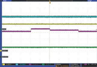
CH1: V(PWM3) CH2: V(PWM4) CH3: V(REF)
CH4: I(IOUT8) Duty cycle = 50% V(SUPPLY), V(EN) = 14 V
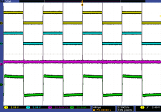
Figure 27. PWM Dimming, Dimming Frequency = 1000 Hz
TPS92638-Q1 scope_p43_slvsck5.gif
CH1: V(REFHI) CH2: V(REF) CH3: I(IOUT1)
CH4: I(IOUT8)
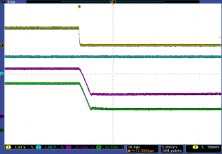
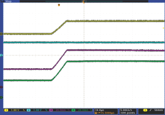
Figure 29. Load Transient, I(IOUTx) Decreases From 70 mA to 35 mA
TPS92638-Q1 D002_SLVSCK5.gif
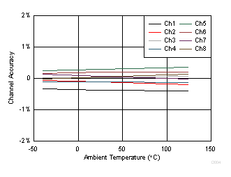
V(SUPPLY) = 12 V
Figure 2. I(IOUTx) Accuracy vs Ambient Temperature
TPS92638-Q1 D004_SLVSCK5.gif
V(SUPPLY) = 40 V
Figure 4. I(IOUTx) Accuracy vs Ambient Temperature
TPS92638-Q1 D010_SLVSCK5.gif
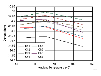
V(SUPPLY) = 5 V
Figure 6. I(IOUTx) Current vs Temperature
TPS92638-Q1 D001_SLVSCK5.gif
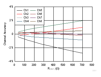
V(SUPPLY) = 12 V TA = 25ºC
Figure 8. I(IOUTx) Channel Accuracy vs R(REF)
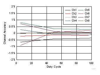
TPS92638-Q1 D006_SLVSCK5.gif
Figure 10. I(IOUTx) Accuracy vs PWM Duty Cycle
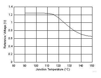
TPS92638-Q1 D012_SLVSCK5.gif
Figure 12. Reference Voltage vs Junction Temperature
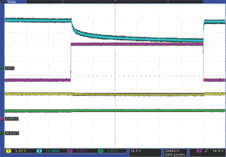
TPS92638-Q1 scope_p28_slvsck5.gif
CH1: V(IOUT1) CH2: I(IOUT1) CH3: V(SUPPLY)
CH4: FAULT
Figure 14. Jump Start From 13.5 V to 26 V
TPS92638-Q1 scope_p30_slvsck5.gif
CH1: V(SUPPLY) CH2: V(REF) CH3: V(IOUT8)
CH4: I(IOUT8) I(IOUTx) = 35 mA
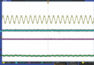
Figure 16. Superimposed Alternating Voltage, 12 V–18 V, 200 Hz
TPS92638-Q1 scope_p32_slvsck5.gif
CH1: V(SUPPLY) CH2: V(REF) CH3: V(IOUT8)
CH4: I(IOUT8) I(IOUTx) = 35 mA
Figure 18. Superimposed Alternating Voltage, 12 V–18 V, 10 kHz
TPS92638-Q1 scope_p34_slvsck5.gif
CH1: V(SUPPLY) CH2: V(REF) CH3: V(IOUT8)
CH4: I(IOUT8) I(IOUTx) = 35 mA
Figure 20. Superimposed Alternating Voltage, 12 V–18 V, 30 kHz
TPS92638-Q1 scope_p36_slvsck5.gif
CH1: V(IOUT1) CH2: I(IOUT1) CH3: V(SUPPLY)
CH4: I(FAULT)
Figure 22. Transient Undervoltage (10.8 V – 9 V – 10.8 V)
TPS92638-Q1 scope_p38_slvsck5.gif
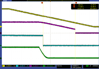
CH1: V(IOUT1) CH2: I(IOUT1) CH3: V(SUPPLY)
CH4: I(FAULT)
Figure 24. Slow Decrease and Slow Increase
TPS92638-Q1 scope_p40_slvsck5.gif
CH1: V(SUPPLY) CH2: V(FAULT) CH3: V(REF)
CH4: I(IOUT8)
Figure 26. Slow Power Down (V(SUPPLY), V(EN), V(PWMx) Fall Together From 14 V to 0 V by 0.2 V/s)
TPS92638-Q1 scope_p42_slvsck5.gif
CH1: V(REFHI) CH2: V(REF) CH3: I(IOUT1)
CH4: I(IOUT8)
Figure 28. Load Transient, I(IOUTx) Increases From 35 mA to 70 mA
TPS92638-Q1 scope_p44_slvsck5.gif
CH1: V(SUPPLY) CH2: V(REF) CH3: V(FAULT)
I(IOUTx) = 35 mA
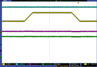
Figure 30. Line Transient, V(SUPPLY), V(EN), V(PWMx) Ramp From 9 V to 16 V to 9 V by 0.1 V/µs