SLUS224G September 1994 – July 2022 UC1842A , UC1843A , UC1844A , UC1845A , UC2842A , UC2843A , UC2844A , UC2845A , UC3842A , UC3843A , UC3844A , UC3845A
PRODUCTION DATA
- 1 Features
- 2 Applications
- 3 Description
- 4 Revision History
- 5 Pin Configuration and Functions
- 6 Specifications
- 7 Detailed Description
- 8 Application and Implementation
- 9 Power Supply Recommendations
- 10Layout
- 11Device and Documentation Support
- 12Mechanical, Packaging, and Orderable Information
Package Options
Mechanical Data (Package|Pins)
Thermal pad, mechanical data (Package|Pins)
Orderable Information
7.3.5 Oscillator
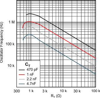
 Figure 7-4 Oscillator Frequency vs Timing Resistance
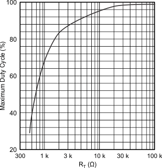
 Figure 7-5 Maximum Duty Cycle vs Timing Resistance
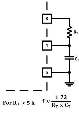
 Figure 7-6 Oscillator Section
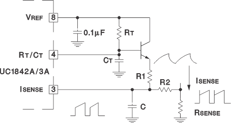
 Figure 7-7 Slope Compensation
Precision operation at high frequencies with an accurate maximum duty cycle, see Figure 7-5, can now be obtained with the UCx84xA family of devices due to its trimmed oscillator discharge current. This nullifies the effects of production variations in the initial discharge current or dead time. Previous versions of the UCx84x devices had greater than a 2:1 oscillator discharge current range and resulted in less reliable maximum duty cycle programming.
A fraction of the oscillator ramp can be resistively summed with the current sense signal, to provide slope compensation for converters requiring duty cycles over 50%. Capacitor C forms a filter with R2 to suppress the leading-edge switch spikes.