SLUSDX3C november 2020 – august 2023 UCC25800-Q1
PRODUCTION DATA
- 1
- 1 Features
- 2 Applications
- 3 Description
- 4 Revision History
- 5 Device Comparison Table
- 6 Pin Configuration and Functions
- 7 Specifications
- 8 Detailed Description
- 9 Application and Implementation
- 10Power Supply Recommendations
- 11Layout
- 12Device and Documentation Support
- 13Mechanical, Packaging, and Orderable Information
Package Options
Mechanical Data (Package|Pins)
- DGN|8
Thermal pad, mechanical data (Package|Pins)
- DGN|8
Orderable Information
3 Description
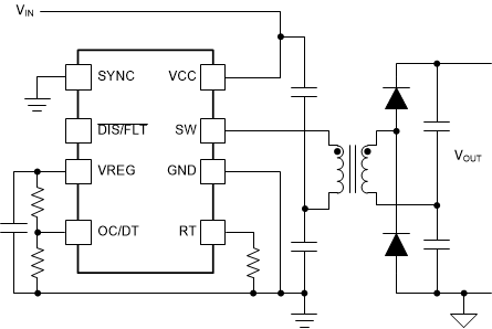
The UCC25800-Q1 ultra-low EMI transformer driver integrates the switching power stage, the control, and the protection circuits to simplify isolated bias supply designs. It allows the design to utilize a transformer with higher leakage inductance, but much smaller parasitic primary-to-secondary capacitance. This low-capacitance transformer design enables an order of magnitude reduction in the common-mode current injection through the bias transformer. This makes the transformer driver an ideal solution for the isolated bias supply in various automotive applications to minimize the EMI noise caused by the high-speed switching devices. The soft-switching feature further reduces the EMI noise.
The transformer driver has a programmable frequency range of 100 kHz to 1.2 MHz. This high switching frequency reduces the transformer size and footprint, as well as the overall cost of the bias supply. The integrated SYNC function allows the system bias supplies to synchronize with an external clock signal, further reducing the system level noise.
The dead-time adjusts automatically to minimize the conduction loss and simplify the design. The programmable maximum dead-time ensures power stage design flexibility.
With the integrated, low-resistance switching power stage, the transformer driver can achieve a 6-W design with 24-V input, and up to 9-W from 34-V input. With a fixed input voltage, the open-loop control also helps the output regulation to remain ±5% when the load is above 10%.
The programmable overcurrent protection (OCP) allows flexibility on the power stage design to minimize the transformer size. The protection features such as adjustable OCP, input OVP, TSD and the protection from pin faults ensure robust operation. A fixed 1.5-ms soft-start period reduces the inrush current during start-up and fault recovery.
The transformer driver also provides a dedicated multi-function pin for external disabling, and fault code reporting. The fault code reporting sends the fault code once the bias supply is in the protection mode.
The UCC25800-Q1 transformer driver is offered in an 8-pin DGN package with the thermal pad to enhance its thermal handling capability.
| PART NUMBER | PACKAGE(1) | BODY SIZE (NOM) |
|---|---|---|
| UCC25800-Q1 | HVSSOP (8) | 3.00 mm × 3.00 mm |
 Simplified Application