JAJSDW2C November   2016  – August 2021 LMS3635-Q1 , LMS3655-Q1

PRODUCTION DATA  

  1. 特長
  2. アプリケーション
  3. 概要
  4. Revision History
  5. Device Comparison Tables
  6. Pin Configuration and Functions
  7. Specifications
    1. 7.1 Absolute Maximum Ratings
    2. 7.2 ESD Ratings
    3. 7.3 Recommended Operating Conditions
    4. 7.4 Thermal Information
    5. 7.5 Thermal Information (for Device Mounted on PCB)
    6. 7.6 Electrical Characteristics
    7. 7.7 System Characteristics
    8. 7.8 Timing Requirements
    9. 7.9 Typical Characteristics
  8. Detailed Description
    1. 8.1 Overview
    2. 8.2 Functional Block Diagram
      1. 8.2.1 Control Scheme
    3. 8.3 Feature Description
      1. 8.3.1 RESET Flag Output
      2. 8.3.2 Enable and Start-Up
      3. 8.3.3 Soft-Start Function
      4. 8.3.4 Current Limit
      5. 8.3.5 Hiccup Mode
      6. 8.3.6 Synchronizing Input
      7. 8.3.7 Undervoltage Lockout (UVLO) and Thermal Shutdown (TSD)
      8. 8.3.8 Input Supply Current
    4. 8.4 Device Functional Modes
      1. 8.4.1 AUTO Mode
      2. 8.4.2 FPWM Mode
      3. 8.4.3 Dropout
      4. 8.4.4 Spread-Spectrum Operation
  9. Application and Implementation
    1. 9.1 Application Information
    2. 9.2 Typical Applications
      1. 9.2.1 General Application
        1. 9.2.1.1 Design Requirements
        2. 9.2.1.2 Detailed Design Procedure
          1. 9.2.1.2.1 Custom Design With WEBENCH® Tools
          2. 9.2.1.2.2 External Components Selection
            1. 9.2.1.2.2.1 Input Capacitors
            2. 9.2.1.2.2.2 Output Inductors and Capacitors
              1. 9.2.1.2.2.2.1 Inductor Selection
              2. 9.2.1.2.2.2.2 Output Capacitor Selection
          3. 9.2.1.2.3 Setting the Output Voltage
          4. 9.2.1.2.4 FB for Adjustable Output
          5. 9.2.1.2.5 VCC
          6. 9.2.1.2.6 BIAS
          7. 9.2.1.2.7 CBOOT
          8. 9.2.1.2.8 Maximum Ambient Temperature
        3. 9.2.1.3 Application Curves
      2. 9.2.2 Fixed 5-V Output for USB-Type Applications
        1. 9.2.2.1 Design Requirements
        2. 9.2.2.2 Detailed Design Procedure
        3. 9.2.2.3 Application Curves
      3. 9.2.3 Fixed 3.3-V Output
        1. 9.2.3.1 Design Requirements
        2. 9.2.3.2 Detailed Design Procedure
        3. 9.2.3.3 Application Curves
      4. 9.2.4 6-V Adjustable Output
        1. 9.2.4.1 Design Requirements
        2. 9.2.4.2 Detailed Design Procedure
        3. 9.2.4.3 Application Curves
    3. 9.3 Do's and Don't's
  10. 10Power Supply Recommendations
  11. 11Layout
    1. 11.1 Layout Guidelines
    2. 11.2 Layout Example
  12. 12Device and Documentation Support
    1. 12.1 Device Support
      1. 12.1.1 Third-Party Products Disclaimer
      2. 12.1.2 Development Support
        1. 12.1.2.1 Custom Design With WEBENCH® Tools
    2. 12.2 Documentation Support
      1. 12.2.1 Related Documentation
    3. 12.3 Receiving Notification of Documentation Updates
    4. 12.4 サポート・リソース
    5. 12.5 Trademarks
    6. 12.6 Electrostatic Discharge Caution
    7. 12.7 Glossary
  13. 13Mechanical, Packaging, and Orderable Information

パッケージ・オプション

メカニカル・データ(パッケージ|ピン)
サーマルパッド・メカニカル・データ
発注情報

概要

LMS3635-Q1 および LMS3655-Q1 同期整流降圧レギュレータは、高性能アプリケーション用に最適化されており、3.3V、5V、または1V~20Vの範囲で調整可能な電圧を出力できます。PWMモードとPFMモードの間でシームレスに遷移し、低い静止電流とともに、あらゆる負荷領域について高い効率と優れた過渡応答を確実にします。

LMS3655-Q1は高度な高速回路を使用しているため、24Vの入力を400kHzの固定周波数で3.3Vの出力にレギュレートでき、5.5Aの連続負荷電流に対応できます。革新的な周波数フォールドバック・アーキテクチャにより、このデバイスはわずか3.5Vの入力電圧からでも、3.3Vの出力をレギュレートできます。入力電圧は最高36Vまで可能で、42Vまでの過渡電圧が許容されるため、入力サージ保護の設計が簡単になります。

フィルタリングと遅延を備えたオープン・ドレインのリセット出力により、システムの真の状態を示すことができます。この機能により、追加のスーパーバイザ部品が必要なくなるため、コストと基板面積を削減できます。

製品情報
型番 パッケージ(1) 本体サイズ
LMS3635-Q1 SON (22) 4.00mm×5.00mm
LMS3655-Q1
利用可能なすべてのパッケージについては、このデータシートの末尾にある注文情報を参照してください。
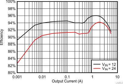
GUID-53F7B7CE-2CF8-4368-9872-535BE2958307-low.gifLMS3655-Q1 の効率:VOUT = 5V
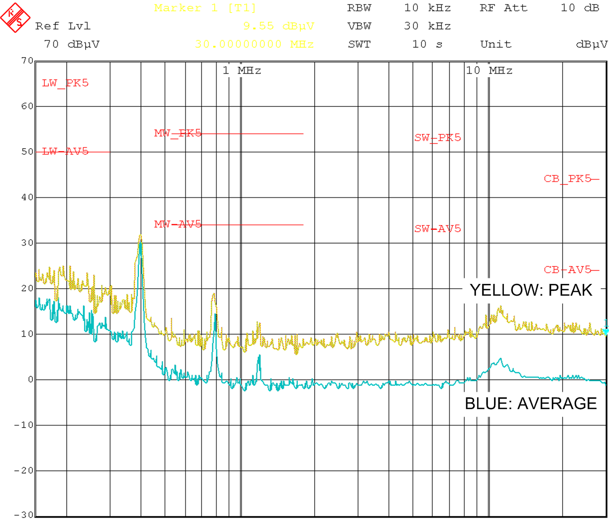
GUID-7E394D33-EEB3-411B-BD79-AC83B59AEEE9-low.pngLMS3655-Q1 の伝導 EMI :VOUT = 5V、IOUT = 5A