JAJSD10B March   2017  – July 2018 LP8863-Q1

PRODUCTION DATA.  

  1. 特長
  2. アプリケーション
  3. 概要
    1.     システム効率
  4. 改訂履歴
  5. Device Comparison Table
  6. Pin Configuration and Functions
  7. Specifications
    1. 7.1  Absolute Maximum Ratings
    2. 7.2  ESD Ratings
    3. 7.3  Recommended Operating Conditions
    4. 7.4  Thermal Information
    5. 7.5  Electrical Characteristics
    6. 7.6  Protection Electrical Characteristics
    7. 7.7  LED Current Sink and LED PWM Electrical Characteristics
    8. 7.8  Power-Line FET and RISENSE Electrical Characteristics
    9. 7.9  Input PWM Electrical Characteristics
    10. 7.10 Boost Converter Electrical Characteristics
    11. 7.11 Oscillator
    12. 7.12 Charge Pump
    13. 7.13 Logic Interface Characteristics
    14. 7.14 Timing Requirements for SPI Interface
    15. 7.15 Timing Requirements for I2C Interface
    16. 7.16 Typical Characteristics
  8. Detailed Description
    1. 8.1 Overview
    2. 8.2 Functional Block Diagram
    3. 8.3 Feature Description
      1. 8.3.1 Control Interface
      2. 8.3.2 Boost Controller
        1. 8.3.2.1 Boost Adaptive Voltage Control
          1. 8.3.2.1.1 FB Divider Using Two-Resistor Method
          2. 8.3.2.1.2 FB Divider Using Three-Resistor Method
        2. 8.3.2.2 Boost Sync and Spread Spectrum
        3. 8.3.2.3 Boost Output Discharge
      3. 8.3.3 2X Charge Pump
      4. 8.3.4 1.8-V LDO
      5. 8.3.5 LED Current Sinks
        1. 8.3.5.1 LED Output Current Setting
        2. 8.3.5.2 LED Output PWM Clock Generation
        3. 8.3.5.3 LED Output String Configuration
          1. 8.3.5.3.1 Independent Cluster Brightness Control Mode
      6. 8.3.6 Brightness Control
        1. 8.3.6.1 Brightness Control Signal Path
        2. 8.3.6.2 Hybrid Dimming
        3. 8.3.6.3 Sloper
        4. 8.3.6.4 Dither
      7. 8.3.7 Die Temperature Read-Out and Thermal Window Detector
      8. 8.3.8 Protection and Fault Detections
        1. 8.3.8.1 LED Faults
        2. 8.3.8.2 Boost Faults
        3. 8.3.8.3 Power-Line Faults
        4. 8.3.8.4 VDD Undervoltage Fault
        5. 8.3.8.5 Thermal Shutdown
        6. 8.3.8.6 Overview of the Fault/Protection Schemes
    4. 8.4 Device Functional Modes
      1. 8.4.1  State Diagram
      2. 8.4.2  Shutdown
      3. 8.4.3  Device Initialization
      4. 8.4.4  Standby Mode
      5. 8.4.5  Power-line FET Soft Start
      6. 8.4.6  Boost Start-Up
      7. 8.4.7  Normal Mode
      8. 8.4.8  Discharge Mode
      9. 8.4.9  Fault Recovery
      10. 8.4.10 Latch Fault
      11. 8.4.11 Start-Up Sequence
      12. 8.4.12 Shutdown Sequence
    5. 8.5 Programming
      1. 8.5.1 Serial Interface Selection
      2. 8.5.2 SPI Interface
      3. 8.5.3 I2C-Compatible Interface
      4. 8.5.4 Programming Examples
        1. 8.5.4.1 General Configuration Registers
        2. 8.5.4.2 Clearing Fault Interrupts
        3. 8.5.4.3 Disabling Fault Interrupts
        4. 8.5.4.4 Diagnostic Registers
        5. 8.5.4.5 Cluster Mode Configuration and Control Registers
    6. 8.6 Register Maps
      1. 8.6.1 FullMap Registers
        1. 8.6.1.1  BL_MODE Register (Offset = 20h) [reset = 300h]
          1. Table 14. BL_MODE Register Field Descriptions
        2. 8.6.1.2  DISP_BRT Register (Offset = 28h) [reset = 0h]
          1. Table 15. DISP_BRT Register Field Descriptions
        3. 8.6.1.3  GROUPING1 Register (Offset = 30h) [reset = 0h]
          1. Table 16. GROUPING1 Register Field Descriptions
        4. 8.6.1.4  GROUPING2 Register (Offset = 32h) [reset = 0h]
          1. Table 17. GROUPING2 Register Field Descriptions
        5. 8.6.1.5  USER_CONFIG1 Register (Offset = 40h) [reset = 8B0h]
          1. Table 18. USER_CONFIG1 Register Field Descriptions
        6. 8.6.1.6  USER_CONFIG2 Register (Offset = 42h) [reset = 0h]
          1. Table 19. USER_CONFIG2 Register Field Descriptions
        7. 8.6.1.7  INTERRUPT_ENABLE_3 Register (Offset = 4Eh) [reset = 200Ah]
          1. Table 20. INTERRUPT_ENABLE_3 Register Field Descriptions
        8. 8.6.1.8  INTERRUPT_ENABLE_1 Register (Offset = 50h) [reset = A02Ah]
          1. Table 21. INTERRUPT_ENABLE_1 Register Field Descriptions
        9. 8.6.1.9  INTERRUPT_ENABLE_2 Register (Offset = 52h) [reset = 80h]
          1. Table 22. INTERRUPT_ENABLE_2 Register Field Descriptions
        10. 8.6.1.10 INTERRUPT_STATUS_1 Register (Offset = 54h) [reset = 0h]
          1. Table 23. INTERRUPT_STATUS_1 Register Field Descriptions
        11. 8.6.1.11 INTERRUPT_STATUS_2 Register (Offset = 56h) [reset = 0h]
          1. Table 24. INTERRUPT_STATUS_2 Register Field Descriptions
        12. 8.6.1.12 INTERRUPT_STATUS_3 Register (Offset = 58h) [reset = 0h]
          1. Table 25. INTERRUPT_STATUS_3 Register Field Descriptions
        13. 8.6.1.13 JUNCTION_TEMPERATURE Register (Offset = E8h) [reset = 100h]
          1. Table 26. JUNCTION_TEMPERATURE Register Field Descriptions
        14. 8.6.1.14 TEMPERATURE_LIMIT_HIGH Register (Offset = ECh) [reset = 7Dh]
          1. Table 27. TEMPERATURE_LIMIT_HIGH Register Field Descriptions
        15. 8.6.1.15 TEMPERATURE_LIMIT_LOW Register (Offset = EEh) [reset = 69h]
          1. Table 28. TEMPERATURE_LIMIT_LOW Register Field Descriptions
        16. 8.6.1.16 CLUSTER1_BRT Register (Offset = 13Ch) [reset = FFFFh]
          1. Table 29. CLUSTER1_BRT Register Field Descriptions
        17. 8.6.1.17 CLUSTER2_BRT Register (Offset = 148h) [reset = FFFFh]
          1. Table 30. CLUSTER2_BRT Register Field Descriptions
        18. 8.6.1.18 CLUSTER3_BRT Register (Offset = 154h) [reset = FFFFh]
          1. Table 31. CLUSTER3_BRT Register Field Descriptions
        19. 8.6.1.19 CLUSTER4_BRT Register (Offset = 160h) [reset = FFFFh]
          1. Table 32. CLUSTER4_BRT Register Field Descriptions
        20. 8.6.1.20 CLUSTER5_BRT Register (Offset = 16Ch) [reset = FFFFh]
          1. Table 33. CLUSTER5_BRT Register Field Descriptions
        21. 8.6.1.21 BRT_DB_CONTROL Register (Offset = 178h) [reset = 0h]
          1. Table 34. BRT_DB_CONTROL Register Field Descriptions
        22. 8.6.1.22 LED0_CURRENT Register (Offset = 1C2h) [reset = FFFh]
          1. Table 35. LED0_CURRENT Register Field Descriptions
        23. 8.6.1.23 LED1_CURRENT Register (Offset = 1C4h) [reset = FFFh]
          1. Table 36. LED1_CURRENT Register Field Descriptions
        24. 8.6.1.24 LED2_CURRENT Register (Offset = 1C6h) [reset = FFFh]
          1. Table 37. LED2_CURRENT Register Field Descriptions
        25. 8.6.1.25 LED3_CURRENT Register (Offset = 1C8h) [reset = FFFh]
          1. Table 38. LED3_CURRENT Register Field Descriptions
        26. 8.6.1.26 LED4_CURRENT Register (Offset = 1CAh) [reset = FFFh]
          1. Table 39. LED4_CURRENT Register Field Descriptions
        27. 8.6.1.27 LED5_CURRENT Register (Offset = 1CCh) [reset = FFFh]
          1. Table 40. LED5_CURRENT Register Field Descriptions
        28. 8.6.1.28 BOOST_CONTROL Register (Offset = 288h) [reset = 1C0h]
          1. Table 41. BOOST_CONTROL Register Field Descriptions
        29. 8.6.1.29 SHORT_THRESH Register (Offset = 28Ah) [reset = 2882h]
          1. Table 42. SHORT_THRESH Register Field Descriptions
        30. 8.6.1.30 FSM_DIAGNOSTICS Register (Offset = 2A4h) [reset = 0h]
          1. Table 43. FSM_DIAGNOSTICS Register Field Descriptions
        31. 8.6.1.31 PWM_INPUT_DIAGNOSTICS Register (Offset = 2A6h) [reset = 0h]
          1. Table 44. PWM_INPUT_DIAGNOSTICS Register Field Descriptions
        32. 8.6.1.32 PWM_OUTPUT_DIAGNOSTICS Register (Offset = 2A8h) [reset = 0h]
          1. Table 45. PWM_OUTPUT_DIAGNOSTICS Register Field Descriptions
        33. 8.6.1.33 LED_CURR_DIAGNOSTICS Register (Offset = 2AAh) [reset = 0h]
          1. Table 46. LED_CURR_DIAGNOSTICS Register Field Descriptions
        34. 8.6.1.34 ADAPT_BOOST_DIAGNOSTICS Register (Offset = 2ACh) [reset = 0h]
          1. Table 47. ADAPT_BOOST_DIAGNOSTICS Register Field Descriptions
        35. 8.6.1.35 AUTO_DETECT_DIAGNOSTICS Register (Offset = 2AEh) [reset = 0h]
          1. Table 48. AUTO_DETECT_DIAGNOSTICS Register Field Descriptions
  9. Application and Implementation
    1. 9.1 Application Information
    2. 9.2 Typical Applications
      1. 9.2.1 Full Feature Application for Display Backlight
        1. 9.2.1.1 Design Requirements
        2. 9.2.1.2 Detailed Design Procedure
          1. 9.2.1.2.1  Inductor Selection
          2. 9.2.1.2.2  Output Capacitor Selection
          3. 9.2.1.2.3  Input Capacitor Selection
          4. 9.2.1.2.4  Charge Pump Output Capacitor
          5. 9.2.1.2.5  Charge Pump Flying Capacitor
          6. 9.2.1.2.6  Output Diode
          7. 9.2.1.2.7  Switching FET
          8. 9.2.1.2.8  Boost Sense Resistor
          9. 9.2.1.2.9  Power-Line FET
          10. 9.2.1.2.10 Input Current Sense Resistor
          11. 9.2.1.2.11 Feedback Resistor Divider
          12. 9.2.1.2.12 Critical Components for Design
        3. 9.2.1.3 Application Curves
      2. 9.2.2 Application With Basic/Minimal Operation
        1. 9.2.2.1 Design Requirements
        2. 9.2.2.2 Detailed Design Procedure
        3. 9.2.2.3 Application Curves
      3. 9.2.3 SEPIC Mode Application
        1. 9.2.3.1 Design Requirements
        2. 9.2.3.2 Detailed Design Procedure
          1. 9.2.3.2.1  Inductor Selection
          2. 9.2.3.2.2  Coupling Capacitor Selection
          3. 9.2.3.2.3  Output Capacitor Selection
          4. 9.2.3.2.4  Input Capacitor Selection
          5. 9.2.3.2.5  Charge Pump Output Capacitor
          6. 9.2.3.2.6  Charge Pump Flying Capacitor
          7. 9.2.3.2.7  Switching FET
          8. 9.2.3.2.8  Output Diode
          9. 9.2.3.2.9  Switching Sense Resistor
          10. 9.2.3.2.10 Power-Line FET
          11. 9.2.3.2.11 Input Current Sense Resistor
          12. 9.2.3.2.12 Feedback Resistor Divider
          13. 9.2.3.2.13 Critical Components for Design
        3. 9.2.3.3 Application Curves
  10. 10Power Supply Recommendations
  11. 11Layout
    1. 11.1 Layout Guidelines
    2. 11.2 Layout Example
  12. 12デバイスおよびドキュメントのサポート
    1. 12.1 デバイス・サポート
      1. 12.1.1 デベロッパー・ネットワークの製品に関する免責事項
    2. 12.2 ドキュメントの更新通知を受け取る方法
    3. 12.3 コミュニティ・リソース
    4. 12.4 商標
    5. 12.5 静電気放電に関する注意事項
    6. 12.6 Glossary
  13. 13メカニカル、パッケージ、および注文情報

パッケージ・オプション

メカニカル・データ(パッケージ|ピン)
サーマルパッド・メカニカル・データ
発注情報

Critical Components for Design

Figure 70 shows the critical part of circuitry: boost components, the LP8863-Q1 internal charge pump for gate-driver powering, and powering/grounding of LP8863-Q1. Schematic example is shown in Figure 70.
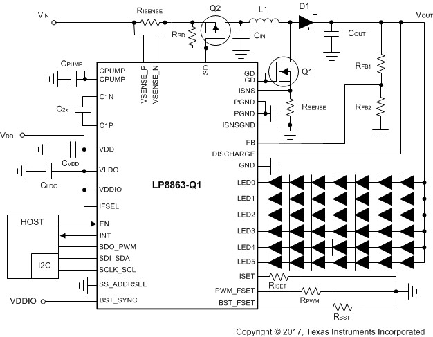
LP8863-Q1 typapp1_snvsab6.gifFigure 70. Critical Components for Full Feature Design

Table 51. Recommended Component Values for Full Feature Design Example

REFERENCE DESIGNATOR DESCRIPTION NOTE
RISENSE 20 mΩ, 3 W Input current sensing resistor
RSD 20 kΩ, 0.1 W Power-line FET gate pullup resistor
RSENSE 20 mΩ, 3 W Boost current sensing resistor
RFB2 100 kΩ, 0.1 W Bottom feedback divider resistor
RFB1 910 kΩ, 0.1 W Top feedback divider resistor
RBST 4.77 kΩ, 0.1 W Boost frequency set resistor
RISET 31.2 kΩ, 0.1 W Current set resistor for 100 mA maximum
RPWM 42.2 kΩ, 0.1 W Output PWM frequency set resistor
CPUMP 10-µF, 16-V ceramic Charge-pump output capacitor
C2X 2.2-µF, 25-V ceramic Flying capacitor
CVDD 4.7-µF + 0.1-µF, 10-V ceramic VDD bypass capacitor
CLDO 4.7-µF + 0.1-µF, 10-V ceramic VLDO bypass capacitor
CIN 2 × 33-µF, 63-V electrolytic + 2 × 10-µF, 100-V ceramic Boost input capacitor
COUT 2 × 33-µF, 63-V electrolytic + 2 × 10-µF, 100-V ceramic Boost output capacitor
L1 22-μH saturation current 23 A Boost inductor
D1 100 V, 10-A Schottky diode Boost Schottky diode
Q1 60-V, 25-A nMOSFET Boost nMOSFET
Q2 60-V, 30-A pMOSFET Power-line FET