DLPU082B August 2021 – August 2022 DLPC7540
- Programmer's Guide
- Trademarks
- 1 Scope
- 2 References
- 3 Acronyms
- 4 System Boot
- 5 System Status
- 6 Version
- 7 Power Modes
- 8 Display Modes
- 9 Source Detection and Configuration
- 10Internal sources
- 11Display Formatting
- 12Image Processing
- 13Illumination Control
- 14Peripherals
- 15Interface Protocol
- 16Command Protocol
- 17Auto-Initialization Batch File
- 18Command Descriptions
- 19System Commands
- Revision History
4.2 Bootloader Application
The bootloader is the first application that runs from the flash memory when the system is turned on or reset. The bootloader application copies itself from flash to internal RAM for execution. This application performs flash update (erase, program). It also identifies a valid main application in the flash and only then begins to run the main application. This application reads the GPIO_64 (HOLD_BOOTZ) signal at the startup and if the signal reads 0, the application remains in the boot application mode. This useful option forces the firmware to update in case the main application on the flash is corrupted. Use the DLP Control Program to update the flash firmware.
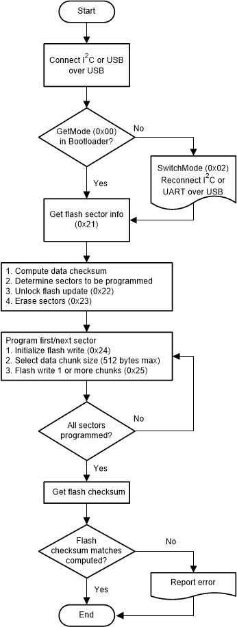
Supported Flash Update Commands lists all commands supported by the bootloader application for flash update. Flash Update Flow Diagram depicts the example usage of bootloader commands for updating the flash contents.
| Command | Description |
|---|---|
| Boot Hold Reason | Reason for controller to be in boot application mode. |
| Get Flash ID | Returns the flash ID |
| Get Flash Sector Info | Retrieve flash number of sectors and sector size information |
| Flash Lock/Unlock | User must send this command to unlock the flash for erase/program access. This is to prevent accidental erase/programming of flash data. |
| Erase Sector | Command to erase sector – user to provide sector address as input |
| Initialize Flash Read/Write | Command to specify start address on the flash along with number of bytes to be written or readback |
| Get Checksum | Command to compute checksum and return it. Command takes flash address and number of bytes to compute the checksum. |
 Figure 4-1 Flash Update Flow Diagram