DLPU109 May 2021
2.4 Programming the DLPC7540EVM and Displaying a SPLASH Image
Follow these steps in order to download and configure the DLPDLC-GUI for DLPC7540 operation:
- Download the DLPDLC-GUI and the Firmware SW package that includes the Firmware binary (.img) files for DLP471TE and DLP650TE.
- Install and open the DLPDLC-GUI
- Setting up Communication Preferences:
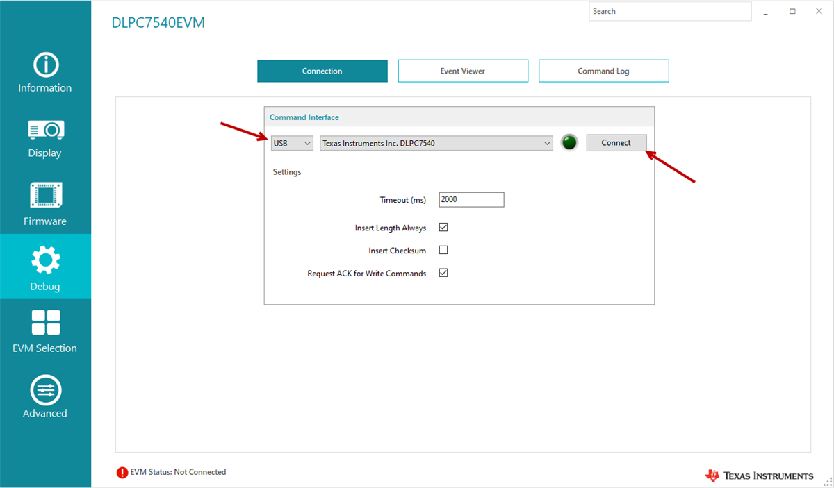
- DLPDLC-GUI supports USB and I2C communication. To change these settings in GUI, please go to Debug screen and select Connection tab.
- For USB, please select the USB interface and click Connect Figure 2-3.
Note: USB is the preferred interface to download the firmware flash
image to the EVM as it is much faster than I2C and won't require any
additional hardware.
 Figure 2-3 Command
Interface Settings
 - Verify that EVM Status shown at bottom left of GUI says Connected, Bootloader Mode indicating you are ready to load image file into EVM.
- Flash Loader Configuration:
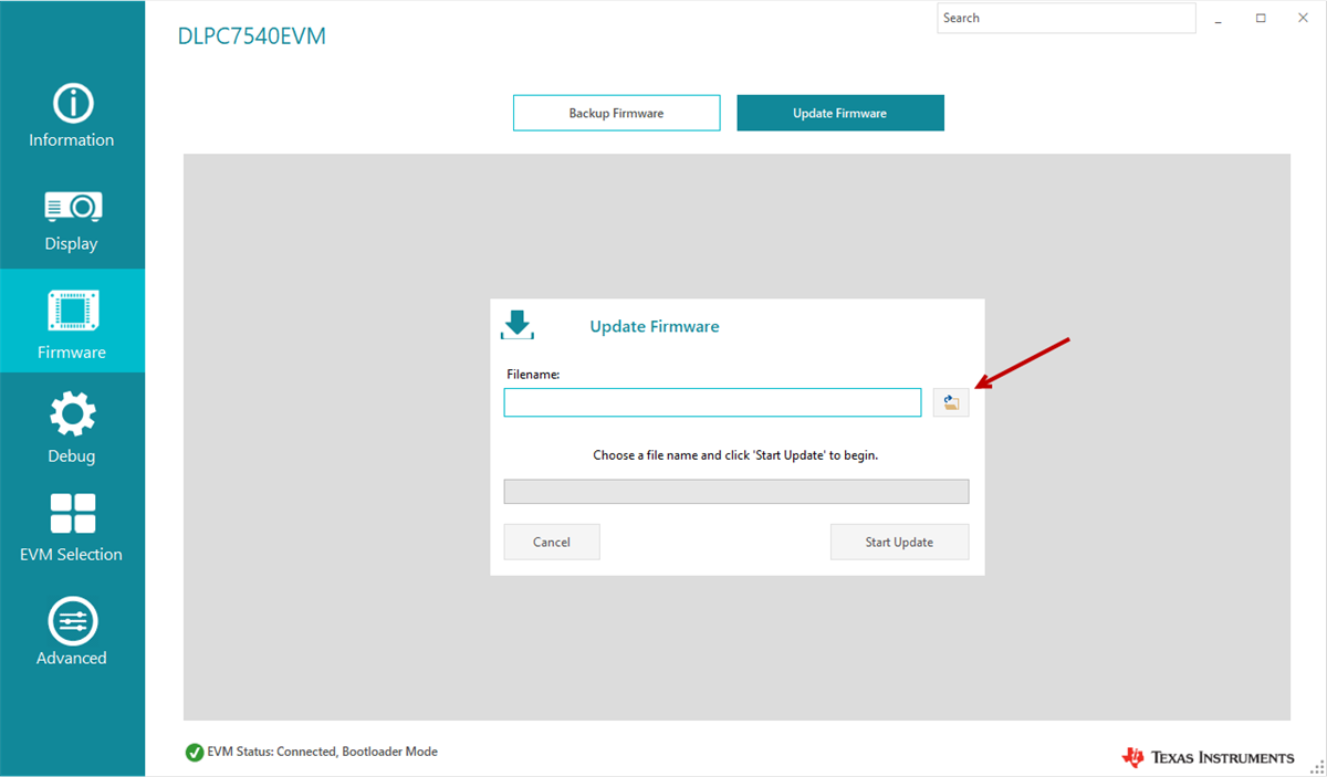
- Go to Firmware screen, select Update Firmware tab. Click on the folder icon to browse for the applicable firmware depending on the actual DMD that is connected to DLPC7540EVM. Once firmware image file is selected, click on Start Update Figure 2-4.
- Wait for the programming progress to indicate that firmware update is complete.
- Turn off the EVM by toggling the SW1 and SW5 switches in that order to off position. Remove the jumper from J9 and install it back to J67.
- Turn on the EVM by toggling the SW5 and SW1 switches in that order to
on position. After about 3 seconds you should see D5, D6, and
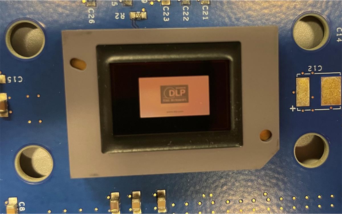
D7 LEDs steadily on and D15 LED flashing. The DLP Texas Instruments logo
should be visible on the DMD Figure 2-5.
 Figure 2-4 Loading the
Flash ImageNote:
Figure 2-4 Loading the
Flash ImageNote:If there is an issue with USB communication, turn off DLPC7540EVM and disconnect then reconnect USB cable and power on board.
 Figure 2-5 Splash Image
Displayed on DMD