JAJU450D November 2015 – March 2020
2.2.4 Inductor Design
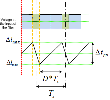
The primary role of the inductor (Li) in the output filter is to filter out the switching frequency harmonics. Amongst other factors, the design of the inductor design depends calculating the current ripple and choosing a material for the core that can tolerate the calculated current ripple. Figure 14 shows one switching cycle waveform of the inverter output voltage Vi with regards to inductor current.

The voltage across the inductor is given by:

For the full bridge inverter with an AC output, write the equation as:

Where  is the switching period. Now, rearrange the current ripple at any instant in the AC waveform, given as:

Assuming the modulation index to be ma, the duty cycle is given as:

The output of the inverter must match the AC voltage as it is safe to assume:

Therefore,

As seen in Equation 7, the peak ripple is a factor of where the inverter is in the sinusoidal waveform (for example, the modulation index). To find the modulation index where the maximum ripple is present, differentiate Equation 7 with regards to time to get Equation 8, and equate to zero.


Equation 9 then gives the modulation index for which the ripple is maximum, substituting back in Equation 7. The inductance value required to tolerate the ripple is shown in Equation 10 and Equation 11:


For this reference design, the rating is 600 VA, the switching frequency is 20 kHz, and the bus voltage is 380 V. Assume that the ripple is 20% and is tolerable by the inductor core, and the minimum inductance required is calculated as:

These calculations are also provided inside an Excel sheet form for convenience located at: C:\ti\c2000\C2000Ware_DigitalPower_SDK_<version>\solutions\tidm_hv_1ph_dcac\hardware\baseboard\calculation.xlsx sheet → UPS Li & Cf Sel.
Select an appropriate core with these values in mind, and the inductor is designed to meet the inductance value.


For this reference design, the rating is 600 VA, the switching frequency is 20 kHz, and the bus voltage is 380 V. Assuming a 20% ripple is tolerable by the inductor core, the minimum inductance needed is calculated as:
<sdk_install_path>\solutions\tidm_hv_1ph_dcac\hardware\baseboard\calculation.xlsx sheet
sheet→Grid Conn. Li, cf, Lg Sel
sheet→LI Design
Select an appropriate core with these values in mind, and the inductor is designed to meet this inductance value.