JAJU450D November 2015 – March 2020
3.1.2.3.2.2 Designing the Current Loop Compensator
- Click the compensation designer icon from the powerSUITE page to launch the compensation designer.
- The plant model for the inverter for the output current loop is created using the parameters specified on the powerSUITE page.
- The compensation designer GUI enables editing the lead lag compensator, which is also a part of Gi
- If a change is required to resonant and PI controller, close the compensation designer and edit the values on the powerSUITE page.
- Save the page.
- Relaunch the GUI.
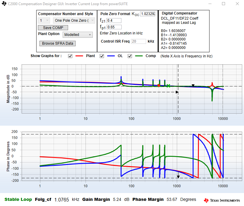
- Verify the stability of the system by observing the gain and phase margins on the open loop transfer function plot in the compensation designer, as shown in Figure 28.
- Once satisfied with the compensation design, click Save COMP.
- Save the compensator values into the project (for example, when the project is recompiled, it will use the new coefficients for the compensator).
- Close the compensation designer and return to the powerSUITE page.
NOTE
If the project is not selected from the solution adapter, the compensator cannot be changed. For a unique design, select the solution through the solution adapter.
