JAJU788A June 2016 – May 2019 TPS3828
5.2 Running Hybrid Wireless M-BUS/PLC Test
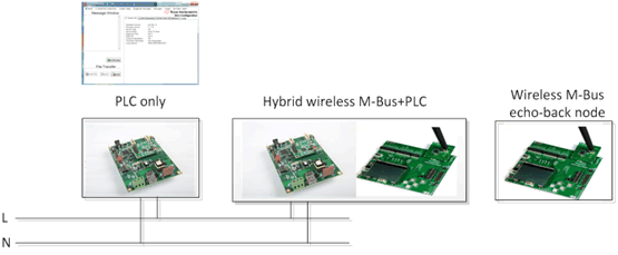
Figure 19 shows a 3-node test set-up. The PLC-only node runs with the zero-configuration GUI tool. The hybrid wireless M-Bus/PLC node and wireless M-Bus echo-back node run in standalone mode.

For the hybrid wireless M-Bus/PLC test, the PLC-only node is configured as G3-PLC mini-DC node. The wireless M-Bus echo-back node may run as an echo-back mode to send back the received wireless M-Bus packet to the hybrid node.
Once the power is on, the hybrid wireless M-Bus/PLC node starts to join to the PLC mini-DC (PLC only node) as the G3-PLC service node. The wireless M-Bus stacks in the hybrid node does not require a joining process. Once joined to the PLC network, the PLC-only node (running as mini-DC) may initiate echo-back data transfer.
NOTE
To bridge echo-back data received from W-MBus node to the PLC mini-DC on the hybrid W-MBus/PLC node, the RF_PLC_REPEATER macro needs to be enabled on the hybrid node and then recompile the software example.
Figure 20 shows the details of the data flow.

- The PLC node sends UDP/IPv6 data through the power line.
- The hybrid wireless M-Bus/PLC node receives the data, and passes the data to the wireless M-Bus echo-back node through the RF path.
- The wireless M-Bus echo-back node takes the UDP/IPv6 header from the received data and then sends it back to the Hybrid wireless M-Bus/PLC node through the RF path
- The hybrid node adds a UDP/IPv6 header on the received data because the G3-PLC only accepts IPv6 packets.
- The hybrid node sends the data to the PLC node through the power line.