SBAA449B October 2020 – October 2021 TMAG5110 , TMAG5110-Q1 , TMAG5111 , TMAG5111-Q1
3.2.1.2 Out-Of Plane Sensor Alignment
With the sensor placed outside of the plane of the magnet ring, there will be a reduction to the observed amplitudes for each component of the B-Field when using an fixed air gap. As a result, there is reduced flexibility for the distance between the sensor and magnet. High sensitivity devices (or devices with a low BOP threshold) allow the application to continue to detect pole transitions even when the device is placed beneath the outer edge. This is particularly helpful in situations where space is limited and the sensor must fit within the magnet diameter.
| Option A - X and Y axes enable the sensor to be positioned facing the side edge of the magnet. It can also be placed with the side edge of the sensor facing the side of the magnet. The device can also be turned at 180° along the Z axis. | 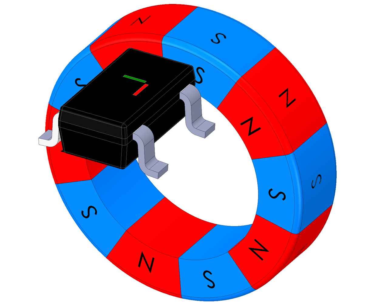 Figure 3-12 XY Side Edge 1 Figure 3-12 XY Side Edge 1 | 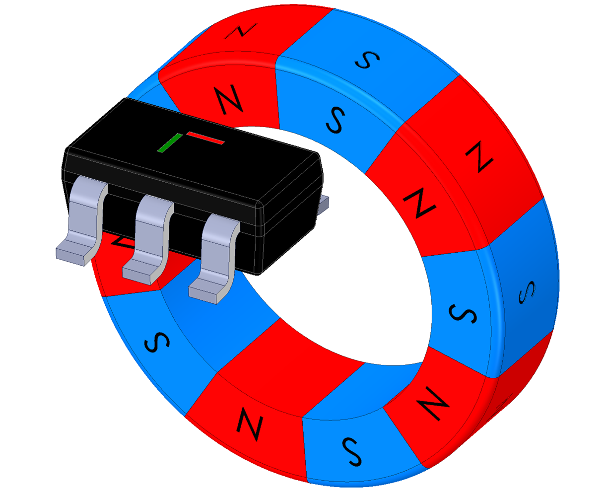 Figure 3-13 XY Side Edge 2 Figure 3-13 XY Side Edge 2 |
| Option B - Z and X axes enable the sensor to be positioned facing the side edge of the
magnet or the top of the package facing the side edge of the magnet. The
device can also be turned at 180° along the Z axis. | 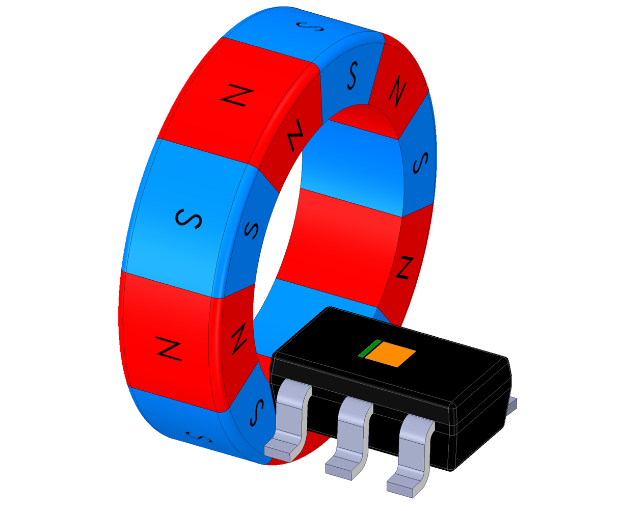 Figure 3-14 ZX Side Edge 1 Figure 3-14 ZX Side Edge 1 | 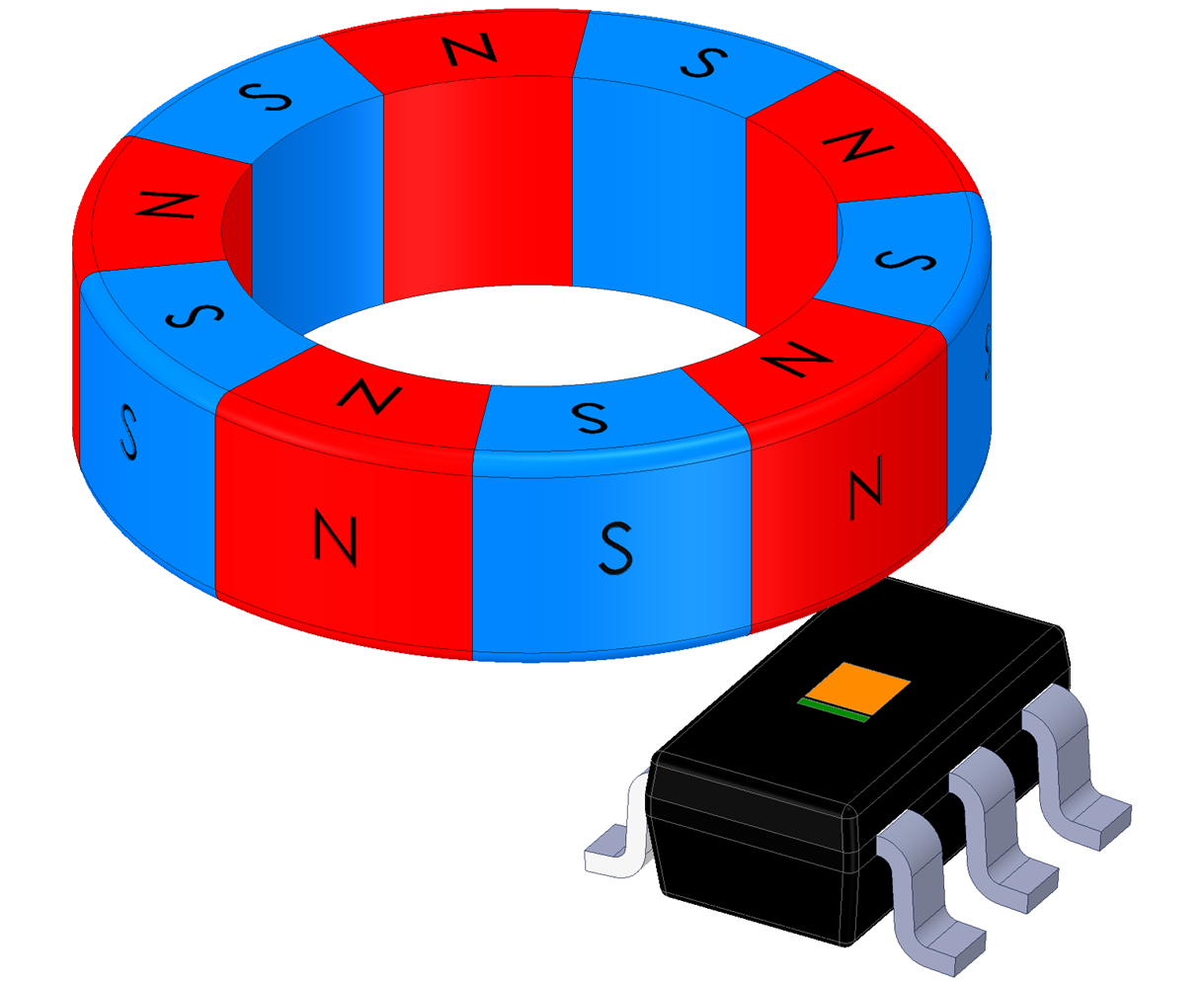 Figure 3-15 ZX Side Edge 2 Figure 3-15 ZX Side Edge 2 |
| Option C - Z and Y axes enable the sensor to be positioned facing the side edge of the
magnet or the top of the package facing the side edge of the magnet. The
device can also be turned at 180° along the Z axis. | 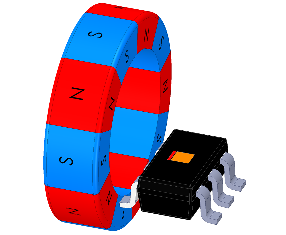 Figure 3-16 ZY Side Edge 1 Figure 3-16 ZY Side Edge 1 | 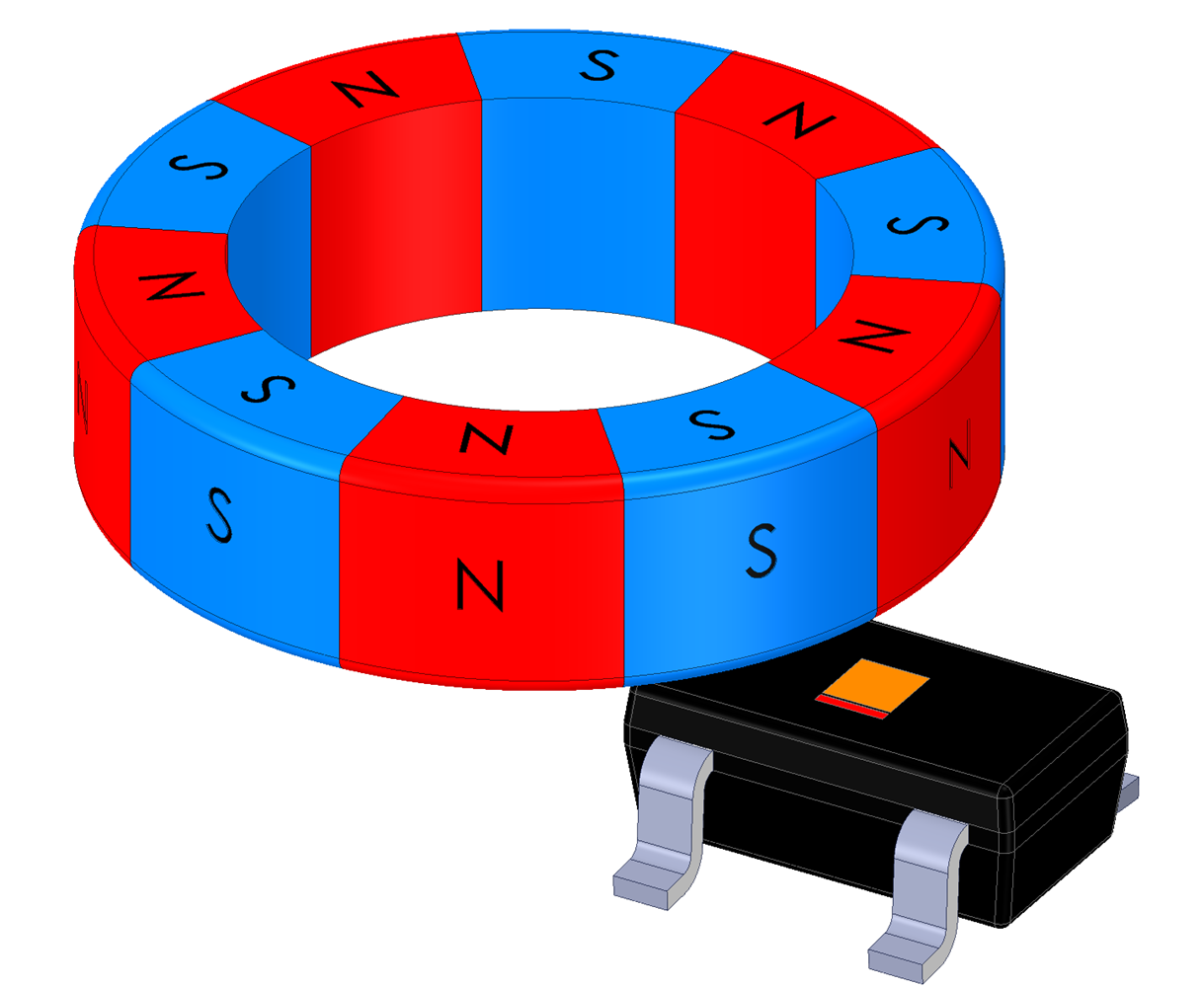 Figure 3-17 ZY Side Edge 1 Figure 3-17 ZY Side Edge 1 |